
An Optical Transceiver is often treated like a small, replaceable part, but in practice it sits at the center of some very visible network headaches. When a link stays down, flaps unexpectedly, or performs worse than expected, the module gets blamed first. Fair enough — though, in many cases, the real issue is somewhere in the optical path, the configuration, or the compatibility layer. That is why a structured troubleshooting approach tends to save time and frustration.
Modern Ethernet and telecom environments rely heavily on optical modules for short-reach and long-reach connections. According to the IEEE 802.3 Ethernet standards, optical links are designed around strict media and signaling requirements, so even a small mismatch can cause failure or instability. Cisco’s guidance on optics compatibility also shows how often vendor support and coding rules shape real-world behavior. In other words, the hardware may look identical, but the network may still refuse to cooperate.
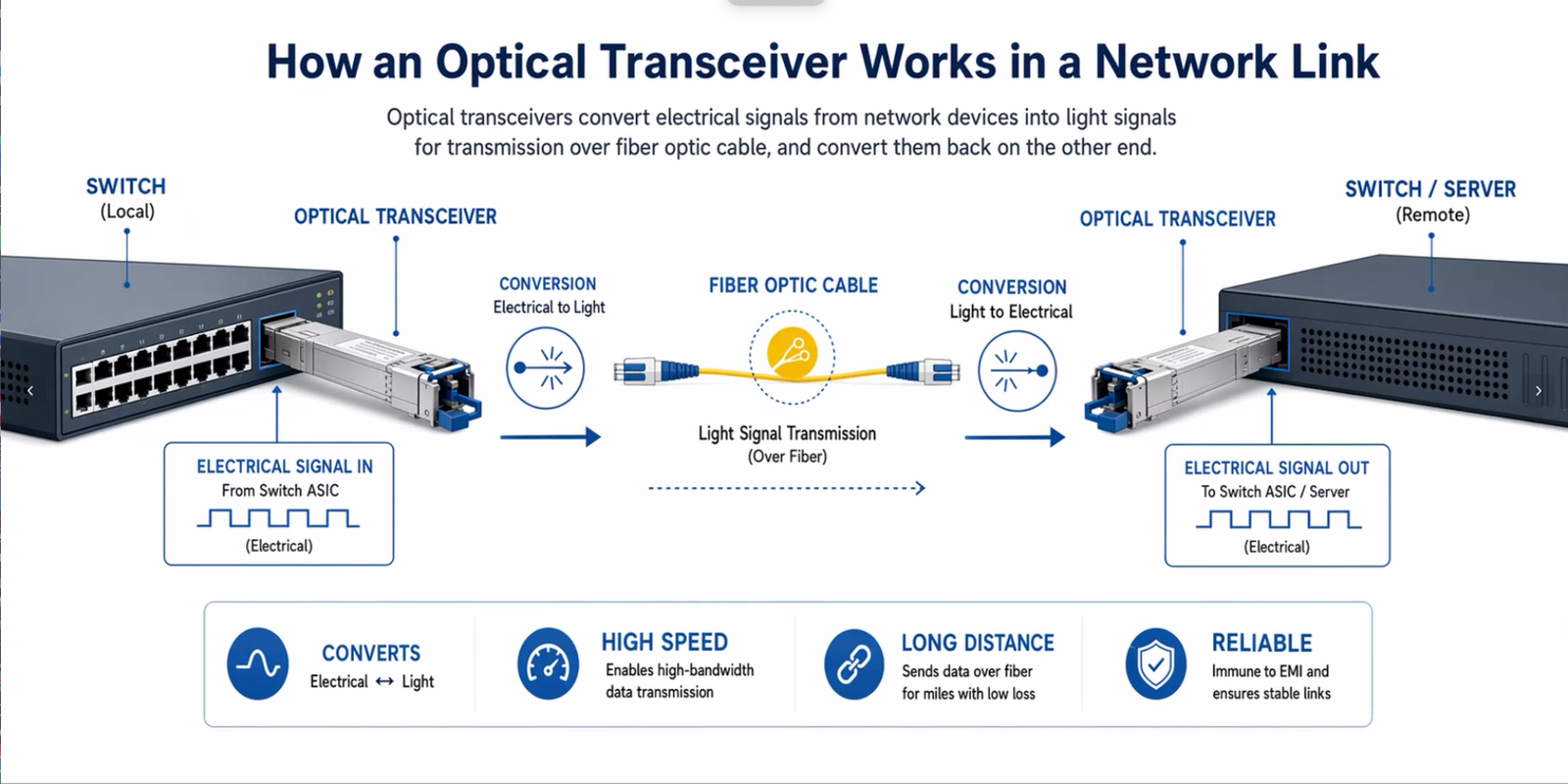
What an Optical Transceiver Does in the Network
Why the module is only one part of the link
An optical module is not working alone. It depends on the switch or router port, the fiber type, the connector condition, the wavelength, and the opposite-end transceiver. A link can fail even when the module itself is technically fine. That is one reason experienced technicians usually start with the full path, not just the optic.
At a high level, the transceiver converts electrical signals into light and back again. But that simple description hides a lot of failure points:
- incorrect fiber type
- bad polarity
- contamination on the connector
- unsupported coding
- insufficient optical budget
- temperature stress
The module may still be reported as “present,” which can be misleading. Presence is not the same as successful data transmission.
The Most Common Optical Transceiver Problems
1. Link not detected
This is probably the most common complaint. The device sees the module, but the port never comes up.
Typical signs include:
- no link light
- the switch shows the optic as inserted but inactive
- the far-end port also remains down
- admin status appears fine, yet data does not pass
Likely causes:
- the module is not supported on that platform
- the speed or form factor is incorrect
- fiber polarity is wrong
- one connector is not fully seated
- the opposite end is misconfigured or missing
2. Link flapping or intermittent disconnects
This issue is especially annoying because it looks random. One moment the link works; the next moment it drops.
Common triggers include:
- loose LC or MPO connection
- dirty endface contamination
- marginal optical power levels
- heat buildup in dense chassis
- a damaged patch cord
- firmware quirks on the host device
Industry support teams often note that intermittent issues are frequently physical-layer problems rather than outright module failure. That pattern holds up in practice.
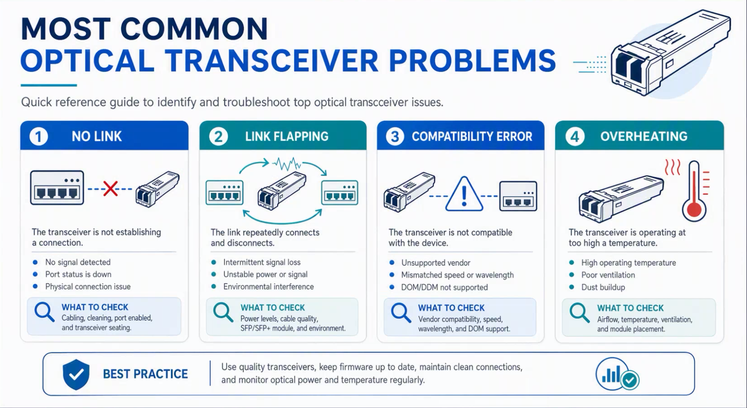
3. Compatibility errors
A transceiver can be electrically and optically healthy, yet still trigger warnings from the switch. Many users have seen messages like “unsupported transceiver” or “transceiver not recognized.”
This usually happens because of:
- vendor coding restrictions
- platform firmware rules
- mismatched speed support
- incorrect wavelength or interface type
- operating system limitations
For this reason, the selection step matters almost as much as troubleshooting itself. A well-matched Optical Transceiver Module reduces surprises before they start.
4. Poor performance or packet loss
Sometimes the link is up, but the performance is not acceptable. Packets drop, throughput is unstable, or latency looks inconsistent.
The likely culprits are often subtle:
- fiber bend radius too tight
- attenuation higher than expected
- old or poor-quality patch cords
- dirty connectors causing reflectance problems
- mixing single-mode and multimode components
- a link operating too close to its power limits
5. Overheating
Optical modules in high-density environments can run hot. That does not always cause an immediate failure, but it can shorten module life or create instability.
Watch for:
- elevated module temperature
- repeated shutdowns under load
- fan airflow problems
- crowded front panels
- high ambient rack temperatures
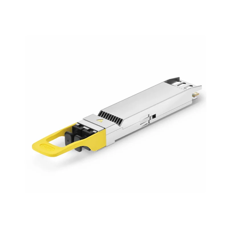
This is especially relevant in modern data centers using high-speed optics, where a 800G Optical Module may be packed into a very demanding thermal environment.
Step-by-Step Troubleshooting Process
Start with the physical layer
This is usually the best first move. It is also the most overlooked.
- Reseat the module.
- Check that both ends click in properly.
- Inspect the fiber patch cord for bends, cracks, or kinks.
- Clean the connectors with proper fiber-cleaning tools.
- Swap the patch cord with a known-good one.
Dirty connectors are a classic cause of trouble. Even when the contamination is microscopic, it can still disrupt the light path enough to reduce signal quality.
Verify compatibility and configuration
After the physical check, confirm the basics:
- correct speed
- correct form factor
- matching wavelength
- appropriate fiber type
- platform support
- firmware compatibility
A common mistake is assuming that any SFP, QSFP, or QSFP-DD module will behave the same way in every device. It will not. The host platform often sets the rules.
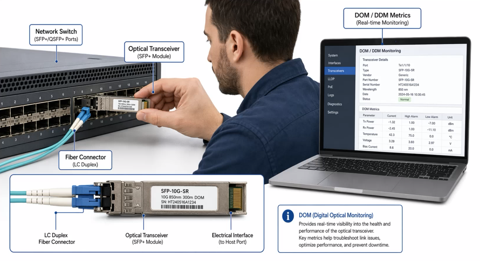
Check DOM/DDM readings
Digital Optical Monitoring, also called DOM or DDM, gives useful clues. These values can point to a marginal link before a full failure happens.
| DOM Parameter | What It Suggests | What to Watch For |
|---|---|---|
| Tx Power | Light being transmitted | Too low may indicate module issues |
| Rx Power | Light being received | Low values may mean attenuation or bad fiber |
| Temperature | Thermal condition of the module | High readings may cause instability |
| Voltage | Module power health | Out-of-range values can indicate hardware issues |
| Bias Current | Laser operating condition | Abnormal levels may suggest aging optics |
If Tx power is normal but Rx power is weak, the problem is probably along the fiber path, not in the module itself.
Test with known-good components
A controlled swap is one of the most reliable troubleshooting techniques. Change only one variable at a time:
- replace the fiber patch cord
- swap the module with a known-good unit
- test the port on a different device
- move the link to another port
This kind of isolation is tedious, but it usually reveals the problem faster than guesswork.
Quick Reference Table: Symptoms and Likely Causes
| Symptom | Most Likely Cause | Practical Fix |
|---|---|---|
| No link after insertion | Unsupported optic or bad seating | Verify support, reseat module |
| Link comes and goes | Dirty connector or loose fiber | Clean ends, replace patch cord |
| Port shows unsupported transceiver | Vendor coding or firmware restriction | Confirm compatibility, update firmware if needed |
| Good link, poor throughput | Optical loss or bend issues | Check DOM, inspect fiber path |
| Module gets very hot | Poor airflow or dense installation | Improve cooling, review rack layout |
When the Problem Is Not the Transceiver
Fiber plant issues
Sometimes the module is innocent. The fiber plant itself may be the real culprit.
Common plant-side problems include:
- polarity reversal
- excessive splice loss
- connector contamination
- damaged cabling
- wrong fiber grade
This is particularly important in older installations where documentation may be incomplete or patch panels have been changed over time.
Switch or router port issues
A port can be disabled, misconfigured, or simply faulty. It is worth checking:
- port admin state
- speed and duplex settings where applicable
- error counters
- platform logs
- firmware version
A hardware fault on the host side can mimic a transceiver issue very convincingly.
How to Reduce Future Optical Issues
The most effective prevention is consistency. In many networks, problems start when optics are mixed too freely or maintenance is delayed.
Good practices include:
- keep dust caps on unused ports
- clean connectors before insertion
- standardize on approved module models
- track inventory by speed and wavelength
- monitor DOM trends over time
- avoid over-bending patch cords
- document device compatibility
It also helps to choose modules based on the actual application, not only on price or headline speed. High-speed environments, in particular, benefit from careful planning, especially when moving toward denser 100G and 400G deployments.
Conclusion
Troubleshooting an optical link usually becomes manageable once the process is broken into layers. Start with the physical connection, confirm compatibility, review DOM readings, and isolate the path with known-good parts. That approach may feel basic, but it is often the fastest way to solve real network problems.
An Optical Transceiver is only one component in a larger chain, and when the chain is healthy, the whole link usually behaves predictably. When it is not, small details matter more than most people expect.
FAQ
Why does an optical module show as detected even when traffic does not pass?
Detection only means the host can identify the module electronically. It does not guarantee that the optical path is healthy, the remote end is ready, or the fiber polarity is correct.
Can a transceiver fail without any obvious DOM alarm?
Yes. Some failures are intermittent or partial. A module may still report acceptable readings while producing unstable light output, especially under heat or vibration.
Is replacing the module always the fastest fix?
Not always. In many cases, cleaning connectors, swapping patch cords, or checking platform compatibility resolves the issue faster and with less cost than replacing hardware.