An optical transceiver is one of those components that sounds more complicated than it usually is. In practice, it is a compact device that sends and receives data by converting electrical signals into light signals and then converting those signals back again. That simple function sits at the heart of many modern communication systems, especially where speed, distance, and reliability start to matter a lot.
It is easy to think of an optical transceiver as a small technical accessory tucked inside a switch or router. That description is not wrong, but it undersells the role it plays. In fiber networks, data centers, telecom systems, and even some industrial setups, this little module often decides whether a connection is smooth, scalable, and stable enough for real-world demand.
Optical Transceiver Basics: What It Does and Why It Exists
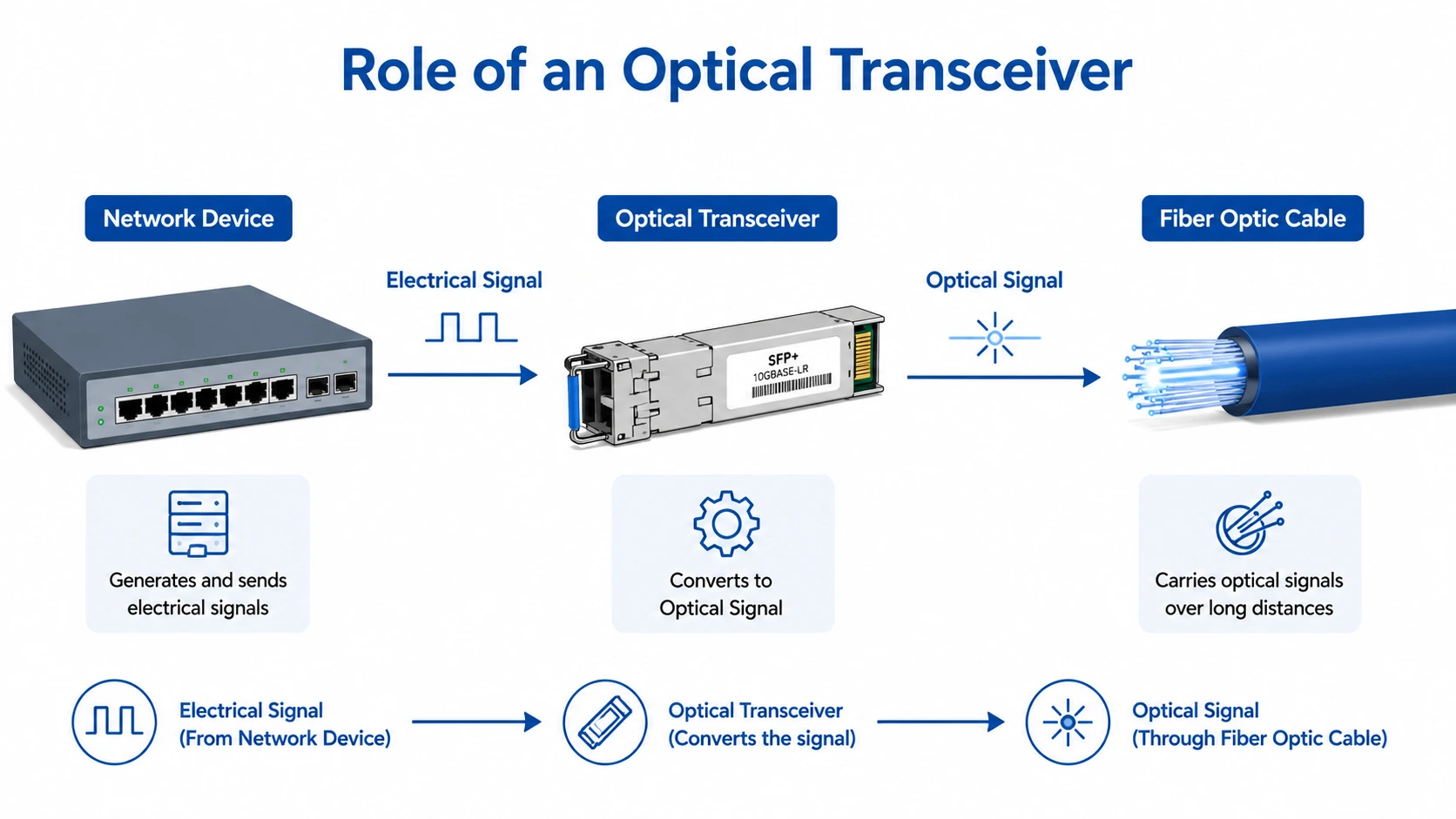
At the most basic level, an optical transceiver exists to bridge two different types of signal transmission.
Electrical signals are what networking equipment naturally uses.
Optical signals are what fiber optic cables carry efficiently over distance.
So the module translates between the two.
That translation is the whole idea. Without it, network devices would not be able to communicate over fiber in a practical way. In a sense, the optical transceiver is the translator sitting between the electronics and the light path. It is not flashy, but it is indispensable.
In many systems, the module is hot-swappable, which means it can often be inserted or removed without shutting down the equipment. That design choice is one reason these devices are so widely used in modern infrastructure. They make upgrades and maintenance less disruptive than they used to be.
For a broader view of available optical transceivers, it helps to think beyond just speed ratings and look at the overall network environment: the cable type, the required distance, the chassis compatibility, and even the ambient heat in the rack
How an Optical Transceiver Works
The working principle is straightforward, although the internal engineering is more refined than it first appears.
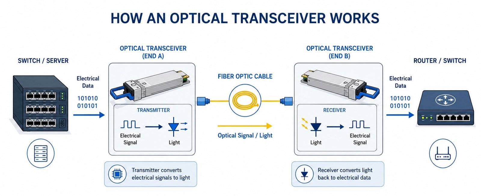
The transmitting side
When the host device sends electrical data into the module, the transmitter section converts that data into pulses of light. A laser or light-emitting component creates the optical signal, and that signal is launched into the fiber.
The fiber carries the light
The light travels through the fiber optic cable with very little signal loss compared with copper at long distances. That is one of the main reasons optical networking became so important in the first place.
The receiving side
At the other end, the receiving section detects the incoming light and converts it back into an electrical signal. The host device can then process the data normally.
The host device keeps everything moving
The switch, router, server, or transmission platform handles the actual network traffic, while the optical transceiver does the conversion work that makes the link possible.
That sequence may sound obvious once laid out, but it is easy to miss how much depends on clean signal conversion. If the transmitter is weak, the receiver is noisy, or the alignment is off even slightly, the whole connection starts to feel less reliable.
Main Parts Inside the Module
Different products use different internal layouts, but most optical transceivers include a few key building blocks.
| Component | Function | Why It Matters |
|---|---|---|
| Light source / laser diode | Produces the optical signal | Determines transmission quality and wavelength |
| Photodetector | Receives light and turns it into electrical data | Affects receiver sensitivity |
| Driver circuit | Controls the transmitter | Helps keep the signal stable |
| Amplifier circuit | Boosts incoming weak signals | Supports accurate reception |
| Connector and housing | Physical interface and protection | Ensures compatibility and durability |
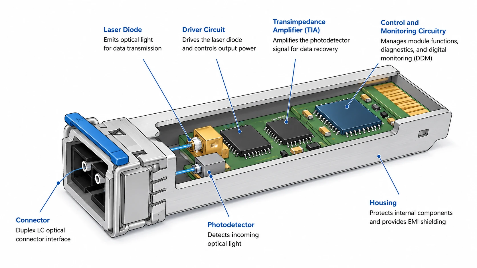
Light source or laser diode
This is the transmitter’s engine, in a way. It generates the optical signal that will travel through the fiber. Different wavelengths are used depending on the application, and that detail matters more than beginners usually expect.
Photodetector
On the receiving side, the photodetector converts incoming light into electrical output. Good sensitivity here is important, especially in links that stretch over longer distances.
Driver and amplifier circuits
These supporting circuits help shape and stabilize the signal. They are not always discussed in basic explanations, but they are part of the reason optical communication can remain dependable under demanding conditions.
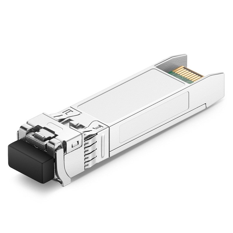
Connector and shell
The outer design keeps the module compact and helps it fit into the host device. The physical interface also ensures that it aligns with the rest of the system properly. Small detail, but a very practical one..
Why Optical Transceivers Matter in Real Networks
The value of an optical transceiver becomes clearer when the network has to do real work.
Fiber-based systems can support higher bandwidth, longer transmission distances, and better resistance to electromagnetic interference than traditional copper in many cases. That is why they are used so often in backbone links, aggregation layers, and high-density systems.
There is also the matter of scalability. As traffic grows, network managers often need to increase speed without rebuilding everything from scratch. That is where modular optical components prove useful. They make changes easier to manage, which tends to matter a great deal once a network gets large enough.
For readers comparing optical transceivers in real deployments, the main question is rarely “Does it work?” It is more often “Does it fit this exact link, this exact distance, and this exact device?”
A few practical advantages stand out:
higher data rates than many copper-based links
lower signal degradation over distance
more efficient use of rack and switch space
better support for modern bandwidth demands
easier upgrades through modular design
That is why the optical transceiver remains a core part of fiber infrastructure rather than just a niche accessory.
For general background on optical communication standards, the International Telecommunication Union is a useful reference, especially when it comes to broader telecom frameworks and transmission practices..

Common Form Factors and Types
Not every transceiver is built the same way. In fact, form factor is one of the first things people notice when comparing products, and for good reason. The shape, size, and interface type usually reflect the network application.
SFP, SFP+, and SFP28
These smaller modules are common in enterprise and data center environments. SFP is widely used for lower-speed links, while SFP+ and SFP28 support higher throughput. They are compact, practical, and still very common.
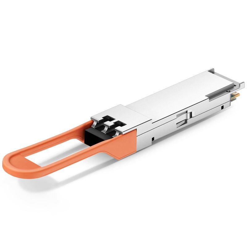
QSFP, QSFP+, and QSFP28
These are designed for higher-capacity applications. They often handle multiple lanes of data and appear in more demanding environments where aggregate bandwidth is a priority.
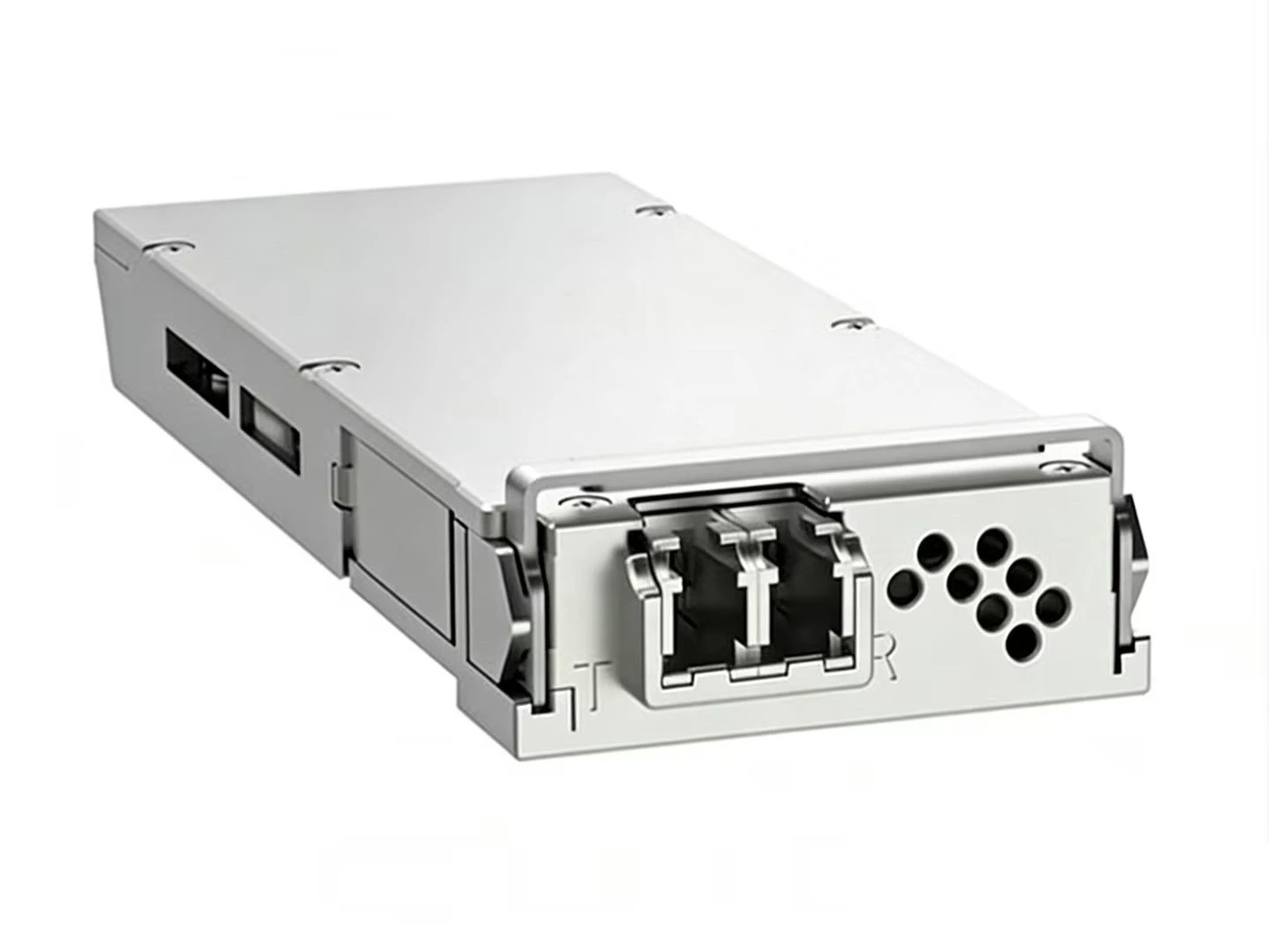
CFP and other larger formats
These modules are generally used in more specialized or high-capacity applications. They are less common in everyday deployments but still relevant in transport and backbone systems.
When reviewing an optical module, it is usually best not to focus on appearance alone. A module that looks similar to another may still differ in speed, wavelength, distance support, or host compatibility. That small gap can make a big difference later.
Optical Transceiver Applications Beyond the Obvious
Most people first encounter optical transceivers in IT and telecom, but the technology reaches further than that.
Data centers
This is one of the most common environments. Servers, switches, storage systems, and interconnects all rely on optical modules to keep traffic moving at high speed.
Telecom and WAN links
Long-distance communications depend heavily on fiber-based transmission, and transceivers are central to that process.
Enterprise and campus networks
Large office campuses and institutional networks often need fiber links between buildings or across floors. Optical modules fit that need nicely.
Industrial and monitoring systems
In specialized environments, fiber technology is also used for sensing and system visibility. That is where optical fiber sensing and monitoring becomes relevant. It extends the idea of optical technology beyond communication alone and into measurement, detection, and infrastructure awareness.
That broader use is a reminder that the same underlying technology can support very different tasks. Communication is the most visible one, but not the only one.
Factors to Consider Before Choosing One
Choosing the right module is less about picking the most powerful option and more about matching the application properly.
Some of the main factors include:
Compatibility with the host device
Required transmission distance
Data rate or link speed
Wavelength support
Single-mode vs. multi-mode fiber
Power usage and heat generation
Environmental conditions
Coding and vendor restrictions
The best choice is usually the one that fits the current network without creating unnecessary complexity. That sounds simple, but in practice it saves a lot of trouble.
A transceiver meant for short-distance connections can perform poorly if it is pushed too far. Likewise, a module that technically fits a port may still be rejected by firmware or fail to meet the expected optical budget. These are the kinds of details that only become obvious after problems appear, which is why checking specs in advance is so important.
Common Mistakes Beginners Make
Some errors show up again and again, especially in first-time deployments.
confusing the transceiver with the fiber cable itself
assuming all modules with the same shape are interchangeable
overlooking distance limitations
ignoring wavelength pairing
failing to check device compatibility tables
treating connector cleanliness as optional
That last one sounds minor, but dirty connectors cause more issues than many people expect. Fiber optics can be surprisingly sensitive to dust, scratches, and careless handling.
Another common mistake is focusing only on speed. Speed matters, of course, but it is only one part of the picture. Distance, signal type, and compatibility often matter just as much.
A Quick Practical Checklist for Deployment
Before installing an optical transceiver, a short checklist can prevent a lot of hassle.
Confirm the host device supports the module type.
Match speed and wavelength to the network design.
Verify whether the link needs single-mode or multi-mode fiber.
Inspect and clean fiber connectors.
Check the power and thermal requirements.
Test the link after installation, not just before it.
A few minutes spent on setup usually pays off later. In network environments, small oversights have a habit of turning into recurring problems.
Conclusion
An optical transceiver is small, but its role is central. It converts electrical signals into light and back again, making high-speed communication possible across fiber networks, data centers, telecom systems, and more specialized applications.
The concept is simple once it is broken down, though the real-world details can get a little technical. Compatibility, distance, wavelength, and form factor all matter. Still, the basic idea stays the same: the optical transceiver is the interface that allows modern network equipment to speak the language of fiber.
And that is probably why it keeps showing up everywhere. It does one job, but it does that job very well.
FAQ
Can an optical transceiver be reused in different network projects?
Often yes, but only if the new project matches the same speed, wavelength, form factor, and compatibility requirements. Reuse is practical, but it is not universal.
What usually limits transmission distance the most?
The main constraints are wavelength, optical power budget, fiber type, and link quality. Device compatibility can also play a role, especially in mixed environments.
Are transceivers and fiber cables the same thing?
No. The cable carries the light, while the transceiver creates and reads the signal. They work together, but they are very different parts of the system.