
Fiber optic networks are usually judged by speed, but in practice, stability matters just as much. A well-chosen Optical Transceiver can make the difference between a clean, reliable link and a connection that looks fine on paper yet behaves unpredictably in the real world. That is especially true in dense enterprise and data center environments, where tiny mismatches can create outsized problems.
Why Optical Transceiver Choice Matters for Fiber Performance
An optical transceiver is more than a hardware accessory. It defines how electrical signals are converted into optical signals, and that conversion has to match the network’s distance, wavelength, and fiber type. Industry guidance from sources like the IEE802.3 standard shows how tightly Ethernet performance is tied to transmission requirements. In other words, the module and the link should be designed to work together.
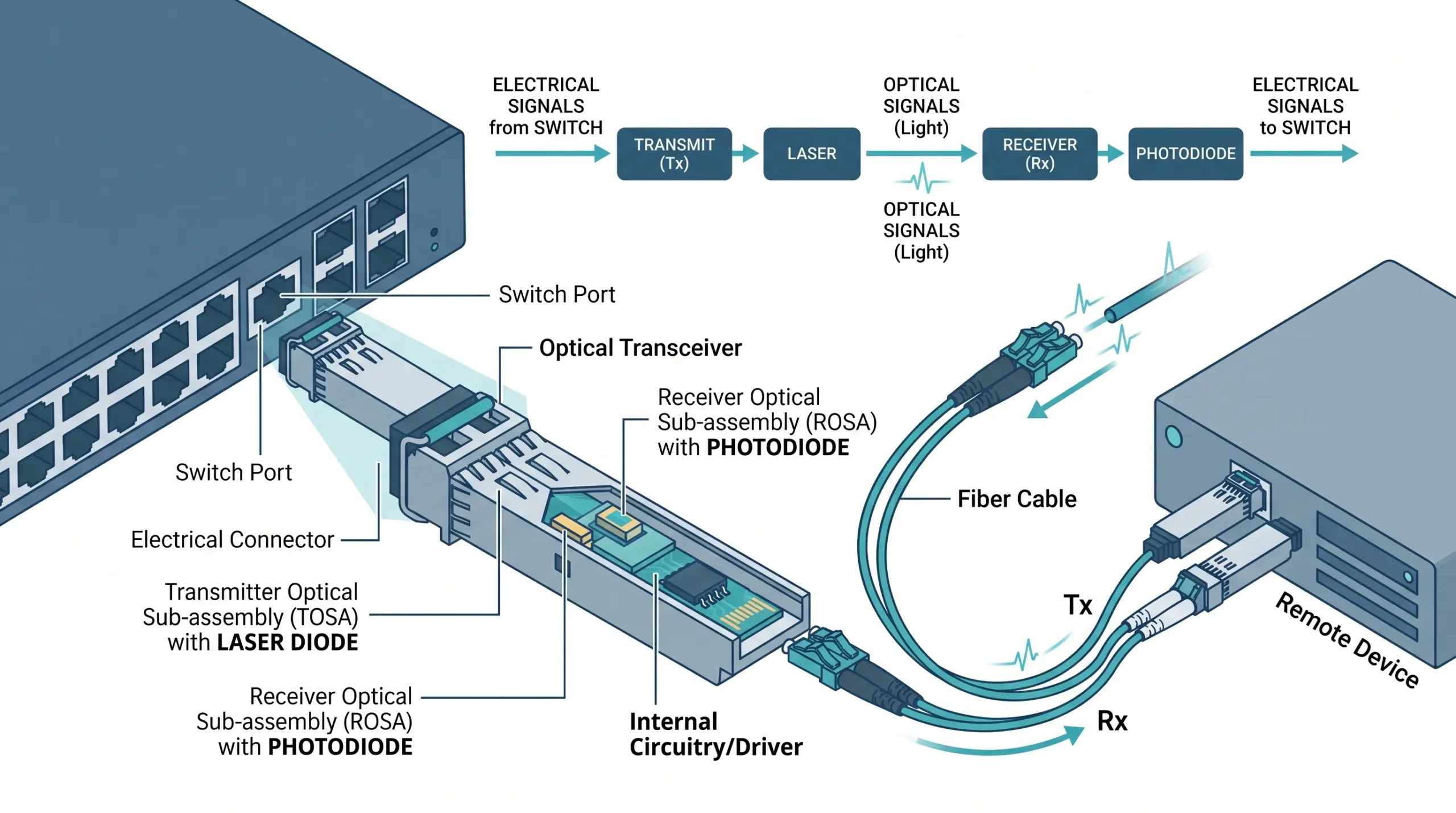
The module is not just a plug-in part
A transceiver may fit the port, but that does not automatically mean it is the right choice. Compatibility issues often appear when:
- the data rate is mismatched
- the wavelength does not align with the fiber plant
- the switch firmware rejects the module
- the module is used beyond its intended reach
How distance, wavelength, and fiber type affect signal quality
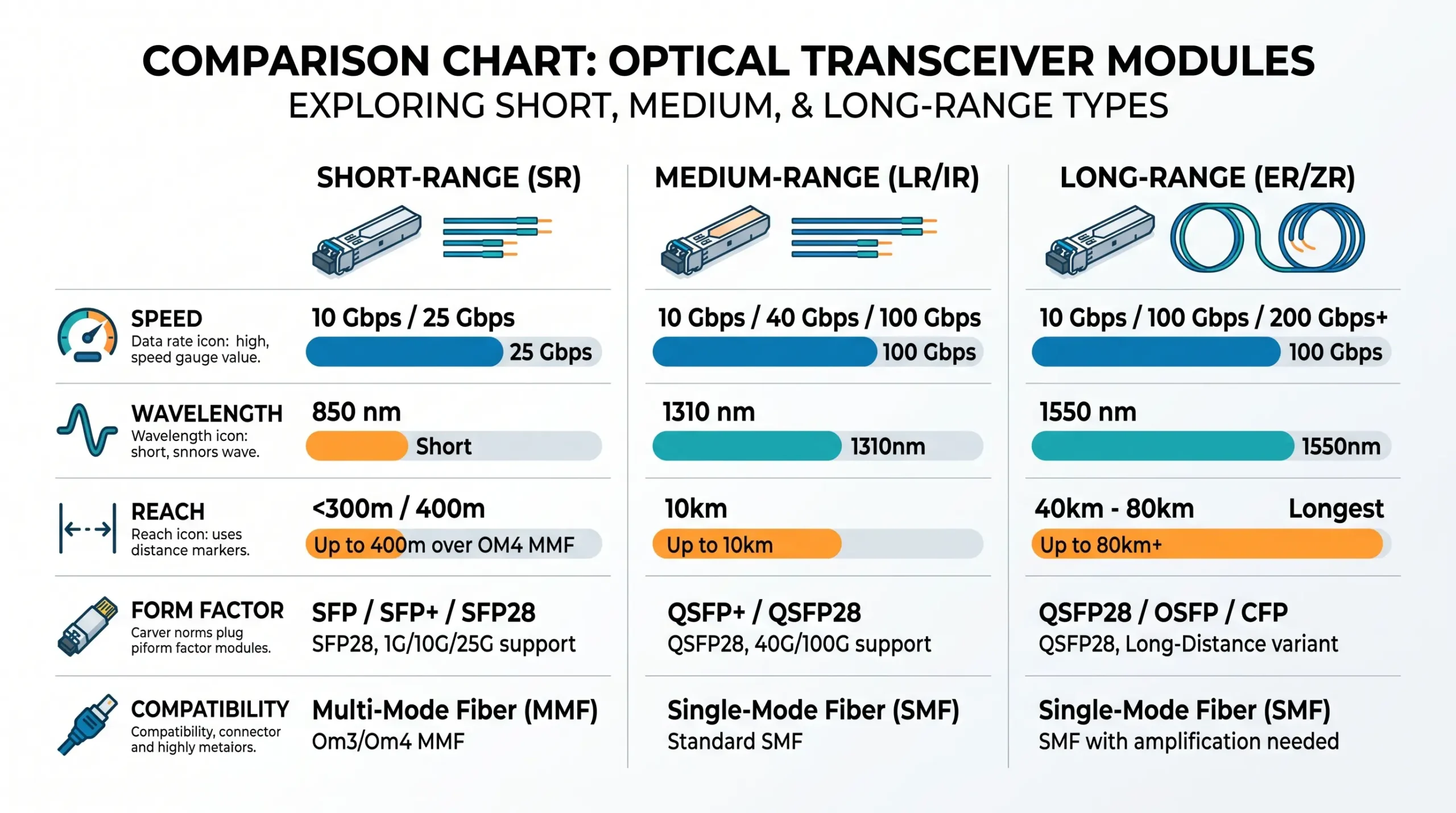
Short-reach multimode links and long-reach single-mode links behave differently. A module that performs well over a short patch run can show loss or errors once the path extends through patch panels and splice points. Wavelength also matters because the optical budget changes with the transmission band. Small differences, especially in crowded routes, can become visible as packet loss or intermittent alarms.
Start with the Right Compatibility Checklist
A lot of troubleshooting starts with the wrong assumption: if the connector fits, the job is done. Usually, it is not.
Match data rate, form factor, and interface type
Before installation, confirm these basics:
- Data rate matches the switch port
- Form factor matches the cage or slot
- Optical interface matches the network design
- Fiber type matches the module spec
- Reach matches the actual cable path
That short checklist avoids many avoidable failures.
Confirm vendor support and switch firmware behavior
Some switches are tolerant; others are picky. In mixed environments, the module may be detected but still trigger warnings or limit performance. Firmware updates can also change compatibility behavior, which is why deployment notes should be checked before mass rollout.
Choose the right module for SMF or MMF links
Single-mode fiber is typically used for longer distances and lower attenuation, while multimode works well in shorter, high-density links. Using the wrong one may not always fail immediately, but it often leads to inconsistent performance.
Cleanliness and Inspection: Small Details, Big Impact
Corning’s cleaning and inspection guidance has long emphasized a simple truth: dirty endfaces remain one of the most common causes of optical problems. Even a tiny contamination spot can disrupt the light path enough to reduce receive power.
Why dirty connectors are still one of the top causes of link loss
A dusty connector may cause:
- higher insertion loss
- unstable receive readings
- intermittent link drops
- permanent endface damage if reinserted repeatedly
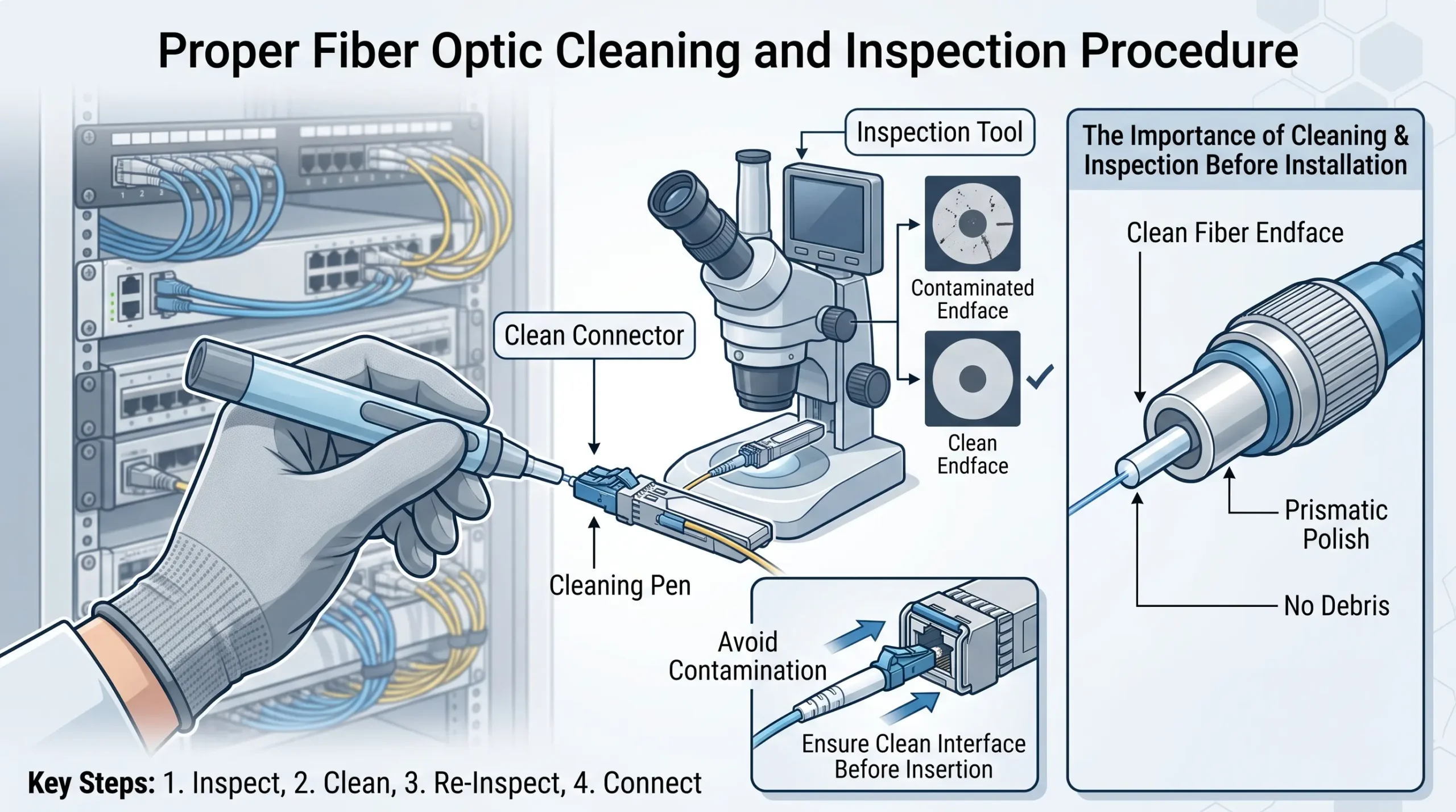
Practical cleaning and inspection steps before installation
Before inserting any module or patch cord:
- inspect the connector endface
- clean with approved tools
- re-inspect under magnification if possible
- avoid touching ferrules directly
- cap unused ports immediately
That routine sounds basic, but in practice it prevents a surprising number of failures.
Use DOM/DDM Data to Spot Problems Early
Digital optical monitoring is one of the most useful features built into modern modules. It provides live information on power and temperature, which makes troubleshooting much easier.
What transmit power, receive power, and temperature can tell you
| DOM/DDM Metric | What It Suggests | Common Cause |
|---|---|---|
| Low RX power | Weak signal at the receiver | Dirty connector, long loss budget, bad splice |
| Low TX power | Source issue or aging module | Faulty transceiver, laser degradation |
| High temperature | Thermal stress | Poor airflow, dense chassis, hot ambient room |
| Fluctuating readings | Intermittent link instability | Loose seating, contamination, vibration |
These readings are especially helpful when the link works at times but degrades under load.
Warning signs that suggest attenuation or overheating
If the module temperature keeps climbing, or the receive power drifts near the lower threshold, the issue may not be the switch at all. It may be the physical path, the cable management, or simply a module that is being pushed too hard in a hot enclosure.
Optimize the Physical Fiber Path
The fiber route itself matters more than many teams expect. Good optics cannot fully compensate for a poor cable path.
Respect bend radius and cable management
Excessive bending can create microbending loss, which is one of those problems that hides in plain sight. Keep bends gentle, route cables cleanly, and avoid compression from tie wraps that are too tight.
Reduce unnecessary patch points and insertion loss
Every extra connection adds some loss. That does not mean patch panels are bad, but it does mean the design should stay as simple as possible. Fewer handoffs generally mean fewer opportunities for contamination, mismatch, or mechanical stress.
When to Consider a 10G Optical Module
For many enterprise and aggregation links, 10G remains a practical balance of speed, cost, and support. A well-matched 10G Optical Module can be a strong choice when the network needs reliable throughput without jumping to a more complex platform.
Best-fit scenarios for 10G links
- campus uplinks
- server aggregation
- storage connectivity
- moderate-distance backbone connections
The key is not just the speed rating, but whether the module fits the actual optical budget and cabling environment.
Common Troubleshooting Patterns and Fixes
Link up but unstable traffic
Check cleanliness first, then verify power levels and bend radius. If the issue appears under load, thermal conditions may be involved.
No link after installation
Confirm module compatibility, fiber polarity, and switch support. A module can look correct while still being wrong for that port profile.
Errors that appear only over longer distances
This often points to budget mismatch, excessive insertion loss, or a module designed for a shorter reach than the link requires.
Final Takeaway
Optimizing fiber optic connections is rarely about one dramatic fix. More often, it is a chain of small decisions: the right Optical Transceiver, clean connectors, sensible cable routing, and real attention to DOM readings. When those basics are handled well, fiber links tend to behave the way they should—quietly, consistently, and with far fewer surprises.
FAQ
How can a network team tell whether the problem is in the transceiver or the cable plant?
A quick clue is the DOM data. If the module reports normal transmit power but poor receive power, the issue often sits in the path rather than the laser. If both directions look abnormal, the module itself becomes a stronger suspect.
Why do some links fail only after equipment is moved or rerouted?
Re-routing usually introduces new bend pressure, extra patch points, or slight connector contamination. The link may survive the move, but performance can quietly drift below the safe margin.
Is it worth standardizing on one module type across a site?
Usually, yes. Standardization reduces compatibility surprises, simplifies spares, and makes troubleshooting faster. It is not always possible, but it is often the cleaner operational choice.