
Tunnels, cable trays, conveyor galleries and pipelines share an awkward property: they are kilometres long, the point where heat will first appear is unknown, and every conventional sensor added costs a cable run, a power drop and a maintenance visit. Covering such routes with point measurement ends in either sparse coverage and blind spots between probes, or a bill that scales with distance. That arithmetic is why linear assets are increasingly specified with a single optical fibre, the basis of distributed temperature sensing systems.
Distributed temperature sensing, normally shortened to DTS, uses an ordinary optical fibre as a continuous thermometer. An interrogator at one end fires short laser pulses into the fibre, reads the faint Raman backscatter returning from every point along the route, and converts the ratio of anti-Stokes to Stokes power into a temperature for each position, located from the round-trip travel time of the light. One fibre therefore produces thousands of readings at roughly one-metre intervals over distances from a few hundred metres to tens of kilometres, with no sensors, no power and no electronics along the route.
The sections below cover the measurement physics, the three specifications that decide whether a quoted system performs, and the field effects that separate a working installation from a datasheet.
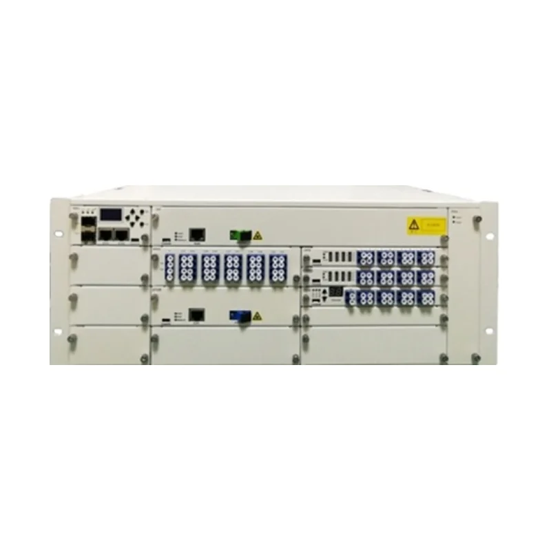
What Is Distributed Temperature Sensing?
Distributed temperature sensing is a method in which the transmission medium is also the sensor. There is no array of discrete probes reporting at fixed locations; temperature is measured continuously along the whole length of the fibre, and the interval between readings is set by the instrument rather than by where a technician could physically install a device.
Three consequences follow. Coverage is continuous, so a hot spot cannot hide between two sensors and the reported position is a distance along the route rather than the nearest instrumented point. The measurement end is passive, which is why the technique suits high-voltage switchyards, tunnels with flammable atmospheres and wells where electronics fail; a fibre carries no current and radiates no signal. The cost is one continuous route per fibre, so a bearing, joint or valve off the route cannot be reached.
One property governs installation more than any specification: the instrument measures the temperature of the fibre, not of the asset. A cable strapped directly to a conductor, a fibre cast into concrete, and a fibre lying loose in a conduit three centimetres from the cable are three different measurements of the same route.
How Does DTS Measure Temperature?
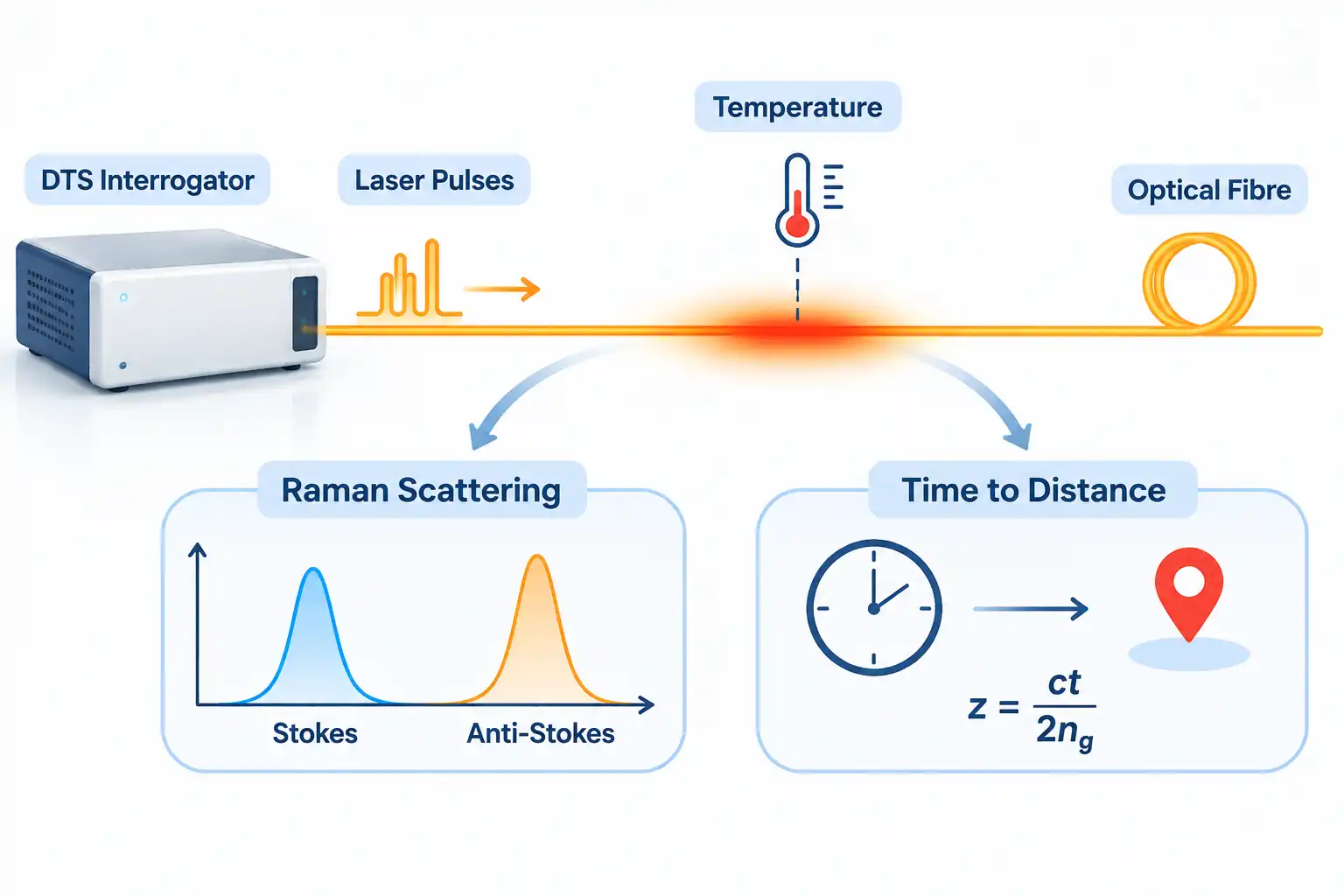
A DTS interrogator launches nanosecond laser pulses into the fibre and measures the small fraction of light that scatters back toward it. Raman scattering creates two sidebands around the launch wavelength, and because the higher-frequency sideband is far more sensitive to temperature than the lower one, the ratio between them yields temperature, while the arrival time of the returned light yields position.
The technique solves two problems with one signal: temperature from intensity, position from timing, and neither depends on the other. The difficulty is signal strength, because Raman backscatter is roughly three orders of magnitude weaker than Rayleigh backscatter, so detectors are cooled or high-gain, filters must reject the pump light, and thousands to millions of pulses are averaged before a value is reported.
Why the Anti-Stokes to Stokes Ratio Works
In silica the Raman shift is about 13.2 THz, so a 1550 nm pump puts the Stokes band near 1664 nm and the anti-Stokes near 1451 nm. Anti-Stokes intensity rises steeply with temperature while Stokes barely moves, giving a ratio of 0.199 at 20 C and 0.316 at 100 C. Relative sensitivity is about 0.74 percent per kelvin at 20 C, falling to 0.45 percent at 100 C, which is why hot measurements need longer averaging. Taking a ratio also cancels launch power and any loss common to both bands.
Turning Arrival Time Into Distance
Light returning after time t came from a distance z = ct/(2ng), where ng is the group index, about 1.468 in silica. A 10 ns pulse therefore averages over about 1.02 m, a 1 ns pulse over about 10 cm. Because the fibre carries one pulse at a time, range also caps repetition rate: 10 km gives a round trip near 98 microseconds, limiting pulses to roughly 10 kHz. The method comes from optical time domain reflectometry, where the same timing resolves distance.
Spatial Resolution, Sample Spacing, and Accuracy Are Not the Same Thing
Three numbers are routinely quoted as though they described one property. Spatial resolution is the shortest temperature feature the instrument can distinguish; sample spacing is merely how densely values are printed and is often several times finer; temperature resolution is the smallest change detectable at one point, and it improves only with averaging time. Confusing them is the most reliable way to buy a system that misses the fault it was bought for.
Spatial resolution in distributed temperature sensing follows a convention: the distance between the points where a step change has reached 10 percent and 90 percent of its final value, as set out in the open textbook literature on fiber-optic distributed sensing. The weighting is roughly Gaussian, so a hot spot narrower than the resolution is smoothed and reads low: a failing conveyor idler produces a patch a few centimetres wide, so a 4 m system reports a rise that never crosses the alarm threshold.
| Parameter | What it defines | Typical value |
| Spatial resolution | Shortest distinguishable feature, by the 10 to 90 percent convention | 1 to 4 m |
| Sample spacing | Interval between reported values, often finer than resolution | 0.5 to 1 m |
| Temperature resolution | Smallest detectable change at one point, after averaging | 0.05 to 1 C |
| Accuracy | Agreement with a reference after calibration | About 1 C |
Temperature resolution is the figure that trades against speed, improving roughly with the square root of measurement time. Any quotation that gives resolution without a measurement time is incomplete.
Single-Ended, Loop, and Multimode Configurations
Most Raman DTS installations are single-ended, with the interrogator at one end of the fibre. A second family of arrangements connects both ends of a loop, and a third variable is the fibre itself: graded-index multimode captures more backscatter and tolerates higher pulse energy, while single-mode preserves resolution over longer distances.
The choice is mostly about calibration burden. A single-ended system must characterise differential attenuation between the two Raman bands at commissioning, because bands about 200 nm apart lose power at different rates and the ratio drifts with distance. A loop measures both ends and cancels that term intrinsically, which suits wells and aggressive environments where the fibre darkens over years.
Channel count is the other lever. Multiplexing four or sixteen channels covers more routes for less capital, but each channel gets a smaller share of instrument time, so update rate or temperature resolution degrades. The IEC 61757-2-2 standard, recorded on the IEC webstore, defines the DTS performance parameters and test procedures, and specifies Raman measurement for single-ended fibre.
What Belongs in a DTS Specification
A specification that can be compared line by line needs more than a resolution figure:
- Spatial resolution, the pulse width it assumes, and sample spacing stated separately.
- Temperature resolution at a stated measurement time, not at an unspecified best case.
- Accuracy, with the calibration basis and reference method named.
- Range per channel, channel count and fibre type.
- Ingress protection, hazardous area certification and output protocol.
The commercial point is simple: a DTS interrogator quoted at 1 m resolution and 0.1 C resolution can be true and useless if those figures need a five-minute measurement on a single channel. Ask for the pair together.
Where DTS Is Used in Practice
Distributed temperature sensing is specified where the route is long, the heat source is unpredictable, and conventional detection either cannot reach the location or cannot survive there. The largest application families are fire detection in tunnels and conveyor galleries, thermal rating of power cables, leak detection on pipelines, and temperature profiling in wells, dams and geotechnical structures.
A tunnel detector reporting only that somewhere in two kilometres it is hot is of little use to a responding crew; one reporting a distance along the ceiling is actionable.
| Application | What the fibre measures | Why DTS fits |
| Road, rail and metro tunnels | Ceiling temperature rise along the bore | Linear coverage with distance-based alarm zones |
| Conveyor galleries, fuel handling | Idler and belt bearing temperature | More hotspots than could be instrumented individually |
| HV cable circuits and trays | Sheath and surface temperature for rating | Continuous profile supports real-time thermal rating |
| Liquid and gas pipelines | Leak-induced thermal anomaly | Gas leaks cool as they expand; liquids shift soil temperature |
| Wells, bores and dam cores | Temperature profile or seepage signature | No electronics at temperature; fibre buried at construction |
Fire detection is the most standardised use. A system acting as a resettable line-type heat detector is assessed against EN 54-22, and products for that market are commonly submitted for national approval and SIL assessment.
How DTS Compares With Other Temperature Sensing Methods
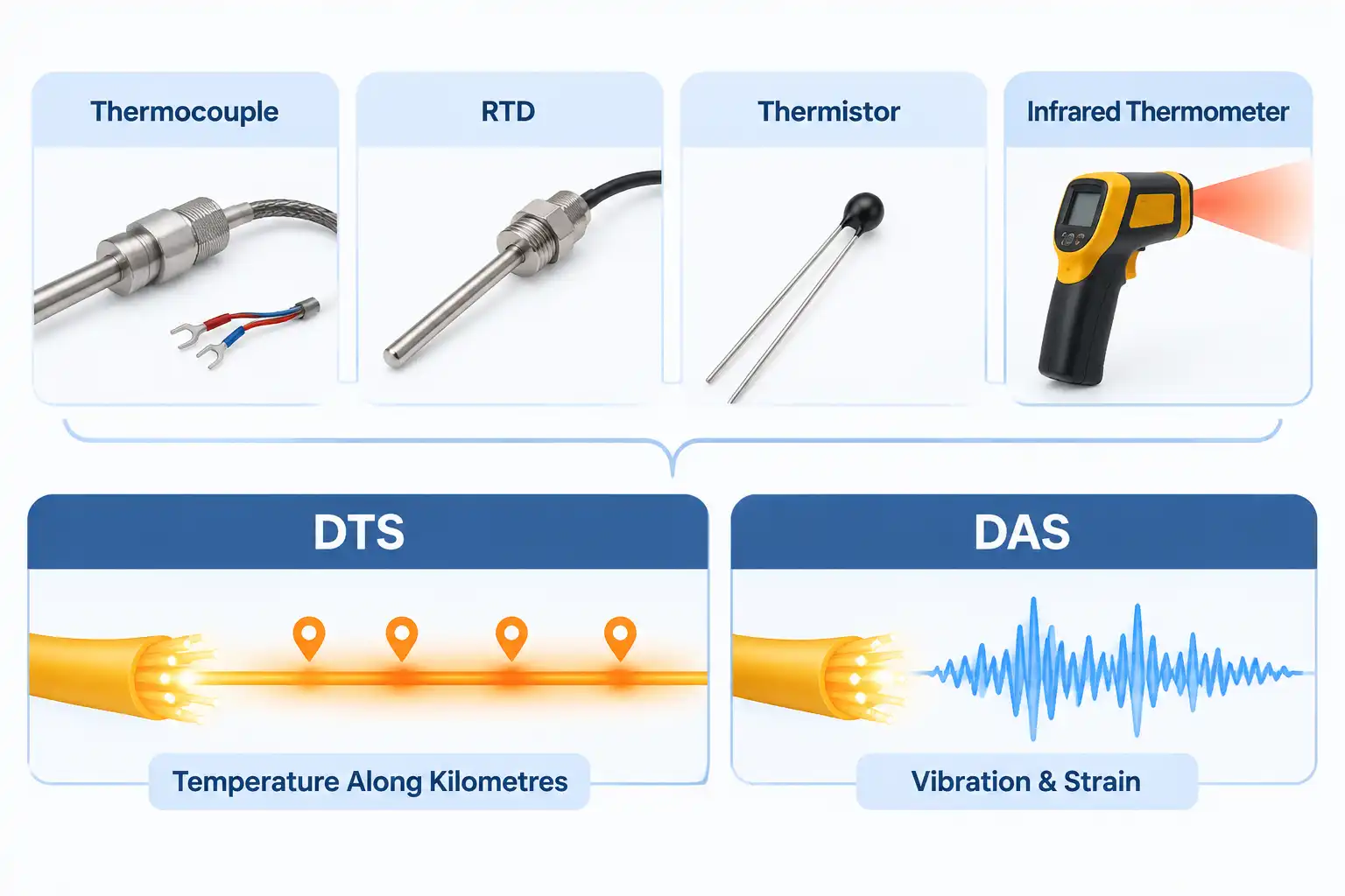
Distributed temperature sensing wins on coverage length and loses on almost everything else, which is the right basis for choosing it. Point sensors are more accurate and cheaper per measurement point, fibre Bragg gratings give better multiplexed point accuracy, Brillouin systems add strain measurement, and Rayleigh-phase systems detect vibration rather than temperature.
Comparing on range alone flatters DTS. Twelve critical bearings are better served by twelve resistance sensors and a logger, because accuracy and response are better and diagnosis is simpler. DTS becomes right when the points you cannot enumerate outnumber the cost of covering all of them.
The Four Conventional Sensor Types
Instrumentation practice groups point temperature sensors into four families. A thermocouple relies on the Seebeck effect at a junction of dissimilar metals and covers the widest range, at the cost of stability. A resistance temperature detector uses the predictable change in a metal’s resistance, usually platinum, and is the most accurate and stable option, though slower and costlier. A thermistor gives the highest sensitivity over a narrow band. An infrared thermometer measures emitted energy without contact, depending on emissivity. None scales to kilometres, and each needs wiring back to a reader.
How Distributed Acoustic Sensing Differs
Distributed acoustic sensing uses the same fibre but a different observable. A coherent interrogator analyses the phase of Rayleigh backscatter rather than Raman intensity, so it reports vibration and strain rate, acting as thousands of microphones at metre spacing. A simpler intensity-based variant, distributed vibration sensing, locates a disturbance but cannot tell stretch from compression.
| Method | What it returns | Main limitation |
| Thermocouple, RTD, thermistor | One temperature per point | Count scales with route length |
| Line-type heat cable | Binary alarm or threshold | Little or no temperature value |
| Fibre Bragg grating | Point strain and temperature | Needs an engineered array |
| Brillouin sensing | Temperature and strain | Slower, cross-sensitive |
| Raman DTS | Temperature profile | Calibration dependent |
| Rayleigh phase sensing | Vibration and strain rate | Not a thermometer |
What Limits DTS Accuracy in the Field
The physics is stable; the installation is not. Three effects account for most field error: differential attenuation between the two Raman bands, hydrogen ingress that darkens the fibre unevenly over time, and drift or loss of the reference section that anchors the absolute scale.
Differential attenuation is a distance-dependent drift; measure the loss difference at commissioning or use a double-ended arrangement. Hydrogen ingress, common in oil and gas wells, and radiation exposure alter fibre attenuation in a wavelength-dependent way, so a calibration valid at installation may drift over years. Every system therefore needs a reference section at a known temperature, a coil inside the instrument or a length of fibre in a bath, to anchor the absolute scale. Connectors and tight bends produce small local steps in apparent temperature that are easy to mistake for real events.
The interaction between range, resolution and averaging is where datasheets get optimistic. A 2026 review of optical fibre sensors reports pulse-coded Raman measurement over 59 km of single-mode fibre at 2 m resolution and 3.9 C accuracy in 330 seconds, a credible field result that also shows what the trade costs. The Raman ratio responds to temperature and is largely insensitive to strain, so a fibre bonded to a structure does not confuse load with heat.
FAQ
Three practical questions come up once the principle is clear and the specification is written.
Can DTS report absolute temperature, or only changes?
Both, and absolute measurement is the normal case for process and fire applications, but it depends on the reference section. An uncalibrated instrument measuring a ratio gives a relative profile that is internally consistent and good for finding anomalies. Absolute values need a length of fibre at a known temperature plus a stored calibration of differential loss. Systems that lose reference integrity drift in absolute terms while remaining useful for trends, which is why calibration records belong in the maintenance file.
How many measurement points does one channel really provide?
Divide range by sample spacing, not by spatial resolution. A 10 km channel sampling every 1 m produces 10,000 values, yet adjacent values are not independent, so the number of genuinely resolved features is closer to range divided by spatial resolution. In alarm design the distinction matters: zoning a route every 5 m when resolution is 4 m creates overlapping zones and alarms that hunt.
Can a DTS system share fibre with live telecom traffic?
Yes, and it is common: the DTS occupies a spare dark fibre inside the same cable as the traffic-bearing fibres, so the sensing fibre itself carries no traffic. If a single fibre must host both, the monitoring channel has to sit at a wavelength far from the traffic bands, the launch power must stay below limits that would impair the traffic, and every connector must be accounted for, since each adds loss plus a reflection that appears as a false temperature step.