The choice of a fiber optimization path determines the long-term scalability of modern network architecture. As enterprise traffic scales exponentially, simple point-to-point fiber runs quickly become economically unviable. This is where wave-division multiplexing shines, splitting a single fiber strand into multiple distinct light channels. Making the final decision between coarse and DWDM methods requires a balanced understanding of technical tolerances, physical distance constraints, and budget realities.
What Is DWDM and How Does It Work?
The dense variant of wavelength division multiplexing operates on a remarkably tight channel spacing framework. By squeezing channels closer together, this specific technology unlocks unprecedented data throughput over a single pair of optical fiber strands.
The Core Mechanics of DWDM
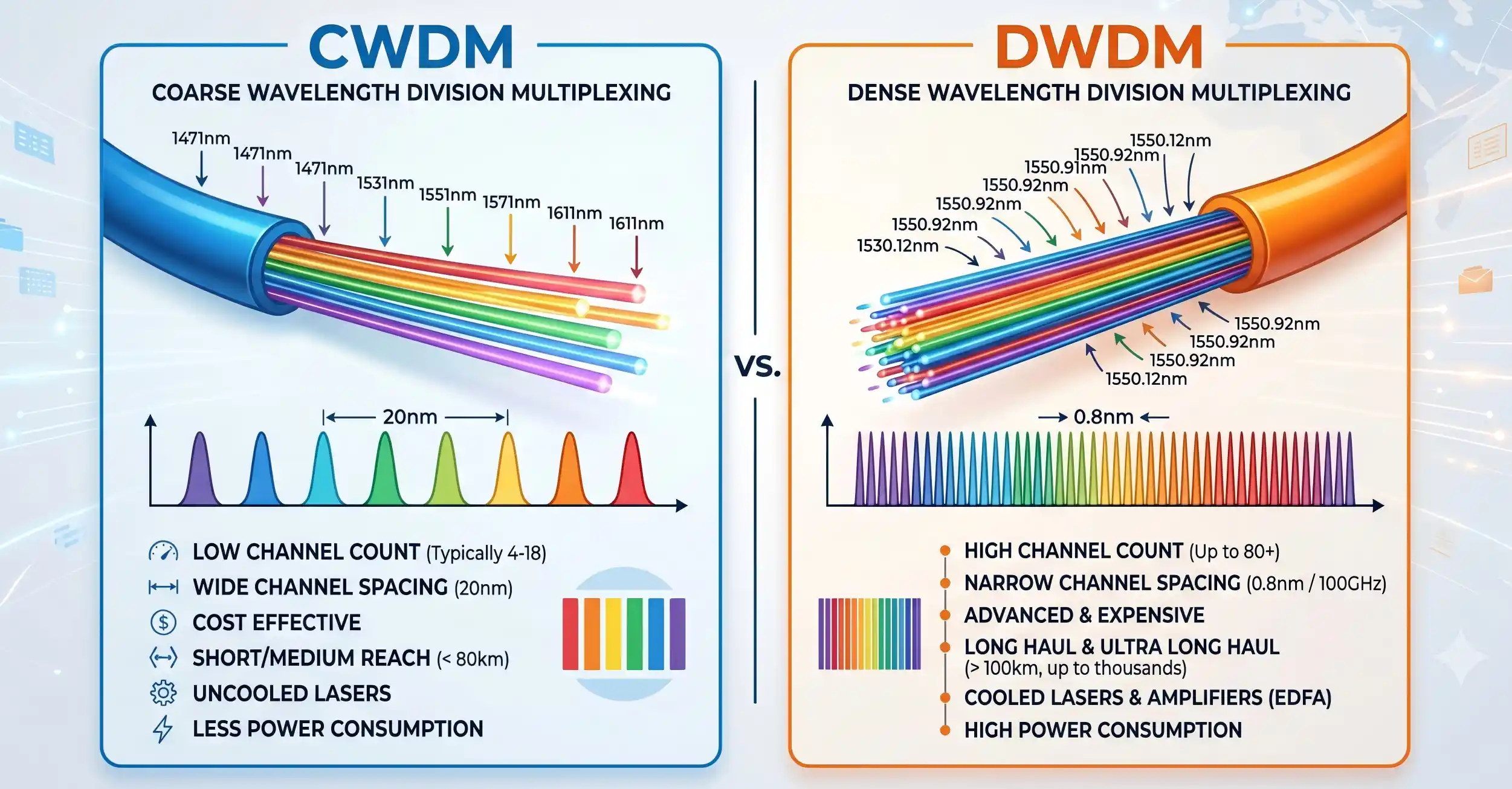
Instead of wide gaps, these platforms utilize a tight grid spacing of 0.8 nm or 0.4 nm (100 GHz/50 GHz frequencies), strictly standardized by the ITU-T G.694.1 grid to ensure multi-vendor interoperability. This extreme precision is vital; fitting dozens of distinct wavelengths into a narrow frequency window leaves zero margin for spectral drift.
The system operates primarily within the conventional band, or C-band (1530 nm to 1565 nm), where silica fiber attenuation hits its absolute lowest point. By packing channels exclusively within this optical sweet spot, network operators maximize the physical efficiency of each glass strand.
However, compressing channels so closely triggers non-linear optical effects, such as Four-Wave Mixing (FWM) and Cross-Phase Modulation (XPM). If optical power levels are unmanaged, these phenomena cause destructive crosstalk across adjacent channels. To counteract this, modern setups combine minimal C-band signal loss with advanced Digital Signal Processing (DSP) at coherent endpoints. This allows high-density architectures to preserve signal integrity over thousands of kilometers, while providing a reliable foundation to expand into the adjacent L-band (1565 nm to 1625 nm) once the C-band reaches saturation.
Key Components in a High-Density System
A functional installation relies on high-precision multiplexers and demultiplexers to combine and separate the optical signals. To dive deeper into the architectural layout and component dependencies, one might review foundational documentation like What Is DWDM in Optical Networking? Benefits, Components, and Applications.
Additionally, high-performance lasers with strict temperature stabilization are mandatory to prevent channels from drifting into adjacent frequencies (a phenomenon known as crosstalk). Unlike coarser methods, these setups frequently incorporate Erbium-Doped Fiber Amplifiers (EDFAs) to boost optical signals directly within the light domain, entirely eliminating the need for costly optical-electrical-optical conversions along the route.
Understanding CWDM: The Coarse Alternative
Coarse Wavelength Division Multiplexing represents a more relaxed, cost-conscious approach to spectral efficiency. It serves as an excellent alternative when extreme capacity isn’t the primary operational metric required by the enterprise.
How CWDM Differs in Wavelength Spacing
The most defining characteristic here is the 20 nm channel spacing, a massive contrast to the fractions of a nanometer used in denser configurations. This wide margin allows the use of uncooled lasers, which inherently reduces manufacturing complexities and overall equipment expenses. The operating spectrum is much wider, stretching across 18 potential channels from 1270 nm to 1610 nm.
This wide 20 nm guard band significantly relaxes the tolerances required for optical filtering components. In practice, manufacturing thin-film filters for coarse networks requires far fewer layers and less stringent calibration than the hyper-precise components used in denser setups. However, a major side effect of utilizing such a sweeping spectral range—stretching from the O-band all the way through the L-band—is that the light signal encounters wildly varying levels of attenuation. Specifically, the notorious “water peak” region around 1383 nm can introduce immense signal loss on legacy fiber cables, effectively forcing network engineers to skip certain channels entirely unless modern, low-water-peak fiber is already pulled through the conduits. Because it relies on these wavelengths prone to higher attenuation, the effective transmission distance is significantly curtailed.
Typical Use Cases for CWDM Networks
For metropolitan area networks or localized enterprise loops, this coarse methodology is incredibly efficient. It allows municipal utilities and regional corporate campuses to maximize existing fiber infrastructure without investing in complex thermal management systems. It plugs a critical gap where immediate capacity expansion is required but the absolute performance of long-distance transport is unnecessary.
Key Differences Between CWDM and DWDM
Evaluating these two architectures involves analyzing a series of performance tradeoffs across capacity, reach, and financial commitment.
Channel Spacing and Capacity
The difference in capacity is stark. A typical coarse installation maxes out at 18 channels, though practical deployment often yields closer to 8 or 16 active channels due to water-peak attenuation in older fiber types. Conversely, high-density systems can comfortably scale to 40, 80, or even 96 channels on a single fiber pair. When paired with modern coherent optics, a single dense run can carry tens of terabits per second, turning a solitary dark fiber thread into a massive data pipeline.
Transmission Distance and Laser Types
Distance limitations fundamentally separate the two approaches. Coarse systems generally top out around 80 kilometers because the optical signals cannot be easily amplified across such a wide spectrum using standard inline amplifiers. Dense platforms, however, utilize highly stable lasers that align perfectly with the amplification bands of EDFAs. This compatibility allows data to travel thousands of kilometers with minimal degradation, making it the bedrock of subsea cables and national backbone architectures. This structural choice impacts the selection of supporting optical transport systems, which must align with the specific distance and amplification requirements of the project.
Cost Considerations (Capital and Operational Expenses)
Financially, the entry point for coarse equipment is substantially lower. The absence of cooling mechanisms in the lasers lowers upfront capital expenditures significantly. High-density hardware requires sophisticated cooling systems and high-tier calibration, raising the initial investment. However, operational expenses can flip the equation over time; if a network outgrows a coarse installation, the cost of laying new physical fiber or completely overhauling the hardware can dwarf the initial premium of a denser setup.

Comparative Overview
| Feature | Coarse Wavelength Division Multiplexing (CWDM) | Dense Variant Technology |
|---|---|---|
| Channel Spacing | 20 nm | 0.8 nm / 0.4 nm |
| Maximum Channels | Up to 18 channels | 40 to 96+ channels |
| Transmission Distance | Short (Up to 80 km) | Long (Thousands of km with amplification) |
| Laser Type | Uncooled (Lower cost, less precise) | Cooled (High precision, temperature-stabilized) |
| Amplification Support | Not practically supported via EDFAs | Fully supported (Inline optical amplification) |
| Initial Cost Profile | Lower Capital Investment | Higher Capital Investment |
How to Choose the Right Technology for Your Network
Selecting the appropriate framework requires a realistic assessment of current traffic loads and expected growth trajectories over a three-to-five-year horizon.
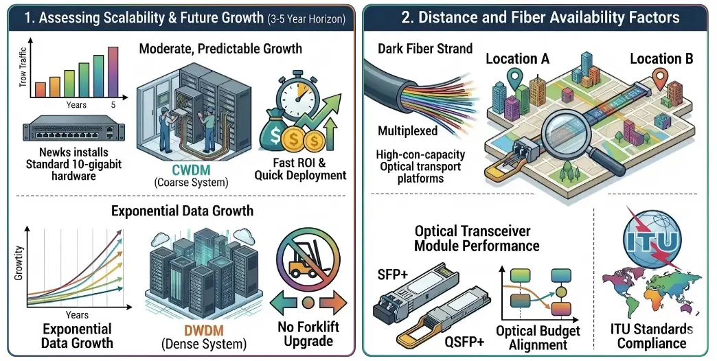
Assessing Scalability and Future Growth
If data center traffic is growing at a moderate, predictable pace, a coarse system might offer the fastest return on investment. It deploys quickly and handles standard gigabit or 10-gigabit traffic with ease. But for cloud providers or media-heavy enterprises experiencing exponential data growth, starting with a dense foundation prevents future forklift upgrades.
Distance and Fiber Availability Factors
When dark fiber leases are expensive or limited, squeezing maximum efficiency out of every strand becomes paramount. In such scenarios, the density of the channels matters more than the hardware premium. The performance of each node hinges heavily on the choice of the optical transceiver module utilized at the endpoints, ensuring the optical budget aligns with the physical path constraints.Moreover, alignment with international telecom standards, such as those maintained by the International Telecommunication Union (ITU), ensures that long-term hardware upgrades remain compatible across standard global networks.
Conclusion: Making the Right Investment in DWDM Technology
Ultimately, the decision isn’t about finding the objectively superior technology, but matching the architectural strengths to specific organizational needs. Coarse multiplexing remains an elegant, budget-friendly champion for short-range local networks that require immediate relief from fiber exhaustion. However, for organizations building toward a future of endless data demands, massive multi-tenant data centers, and long-haul intercity spans, committing to a high-capacity deployment centered on DWDM technology ensures the underlying infrastructure will not become a bottleneck.
FAQ
Why is DWDM preferred for long-haul telecommunications over CWDM?
The dense architecture utilizes narrow channel spacing that fits perfectly within the operational spectrum of Erbium-Doped Fiber Amplifiers (EDFAs). This allows the optical signals to be boosted mid-route without turning the light back into electrical signals, enabling data to travel thousands of kilometers. Coarse systems spread channels across a wide 20nm spacing that cannot be uniformly boosted by standard inline optical amplifiers, limiting them to shorter runs.
Can coarse and high-density optical systems coexist on the exact same fiber strand?
Yes, they can coexist through a hybrid architecture often referred to as upgrading a coarse network with dense wavelengths. Because the coarse channels span a massive range, the entire dense spectrum (which sits tightly inside the C-band) can actually be passed through a single existing coarse channel slot (typically the 1530nm or 1550nm channel), effectively multiplying the capacity of an older installation.
How do environmental temperatures affect high-precision optical components?
High-precision dense systems require active thermal management, usually via internal thermoelectric coolers built into the optics. Because the channel spacing is incredibly tight (fractions of a nanometer), even minor temperature fluctuations can cause the laser’s wavelength to drift, leading to signal interference with neighboring channels. Coarse systems, with their wide 20nm buffers, can tolerate temperature shifts without requiring active cooling mechanisms.