The relentless expansion of cloud environments, high-frequency data replication, and distributed enterprise applications places an unprecedented strain on foundational optical networks. When expanding a dark fiber infrastructure becomes cost-prohibitive, integrating DWDM platforms provides a high-capacity alternative. Instead of undertaking the disruptive and financially draining process of trenching new physical fiber lines, capitalizing on high-density spectral efficiency allows network operators to split a single optical fiber pair into dozens of independent, high-speed data pathways.
Transitioning an active production network from legacy, single-wavelength configurations or lower-density multiplexing systems requires a meticulous, systematic approach. It demands a clear understanding of optical physics, physical plant limitations, and structural hardware dependencies to ensure a seamless migration that maintains network uptime.
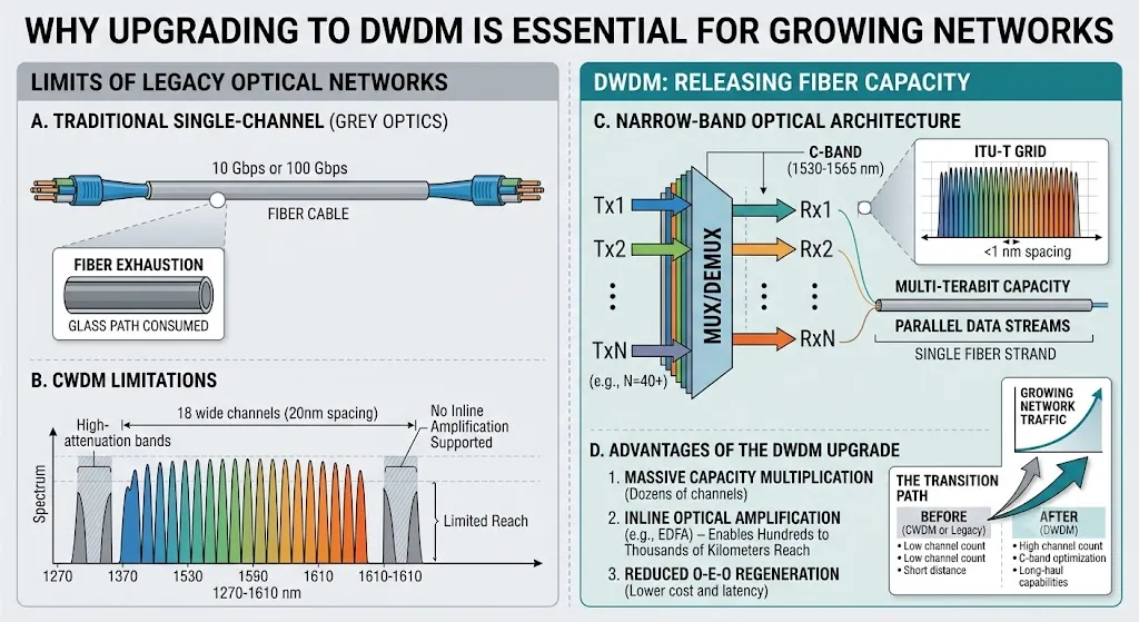
Why Upgrading to DWDM Is Essential for Growing Networks
Modern traffic patterns are no longer predictable or localized; they are volatile, massive, and continuously expanding. Legacy optical transport methods that rely on basic grey optics (standard single-wavelength transceivers) utilize only a fraction of the native information-carrying capacity inherent in modern silica fiber strands.
Overcoming the Physical Limits of Traditional Fiber Architecture
Standard single-mode fiber infrastructure inherently possesses a massive usable bandwidth spectrum, primarily clustered around the ultra-low attenuation windows of silica glass. Traditional single-channel network topographies utilize a single wavelength (often 1310nm or 1550nm) to transmit data. This approach consumes the entire physical glass path for just one stream of traffic, creating an artificial ceiling on throughput.
When that specific channel reaches its maximum data rate limit—whether that is 10 Gbps or 100 Gbps—the fiber is considered exhausted. Overcoming this physical limitation without digging up streets to lay more cables requires dividing the existing spectrum into ultra-narrow channels. High-density wavelength multiplexing achieves this by compressing channel spacing to less than a single nanometer, enabling dozens of parallel data streams to operate concurrently over the exact same physical glass medium.
Accelerating the Transition from Legacy to High-Capacity Transport Systems
Many regional enterprise networks and municipal loops initially scaled their infrastructure using coarse wavelength division multiplexing (CWDM). While that methodology provided an accessible entry point due to its reliance on inexpensive, uncooled laser components, its wide 20nm channel spacing restricts the total channel count to a maximum of 18. Furthermore, those 18 channels span across high-attenuation spectral bands, preventing the use of standard inline optical amplification.
Upgrading to a high-density, narrow-band optical architecture shifts the network operations entirely into the conventional optical band (C-band). This shift unlocks massive multi-channel capacity and enables the integration of inline optical amplifiers, allowing high-capacity data streams to span hundreds or thousands of kilometers without the latency and expense associated with repetitive optical-electrical-optical (O-E-O) regeneration points.
Auditing Your Current Infrastructure Before the Upgrade
A successful network overhaul does not begin at the procurement stage; it starts with a brutal assessment of the existing physical plant. Light waves packed tightly together behave differently than isolated, wide-band signals, making a comprehensive link audit non-negotiable.
Fiber Type Compatibility and Attenuation Testing
Not all single-mode fiber installations are created equal. Legacy G.652 standard single-mode fiber exhibits different chromatic dispersion characteristics in the C-band compared to G.655 non-zero dispersion-shifted fiber (NZDSF). Understanding the exact formulation of the fiber resting in the ground is paramount.
Before introducing narrow-band wavelengths, field engineers must deploy Optical Time-Domain Reflectometers (OTDRs) and optical loss test sets to measure total link loss, localized splice reflections, and macro-bends.
Critical Consideration: At high data rates (such as 100G and beyond per channel), physical anomalies like Chromatic Dispersion (CD) and Polarization Mode Dispersion (PMD) can cause light pulses to spread out and overlap, leading to severe bit-error rate (BER) spikes. Identifying these dispersion values ahead of time dictates whether the system will require passive dispersion compensation modules or specialized coherent end-point optics.
Evaluating Existing Optical Transport Systems
Upgrading the network requires verifying whether current chassis enclosures, patch panels, and software management utilities can support high-density configurations. Legacy optical transport systems might lack the slot density, power budget, or thermal cooling capacity required by active transponder cards or optical amplification units.
Furthermore, checking the mechanical condition of fiber distribution frames is vital. High-density configurations are incredibly sensitive to dirty connectors; a microscopic speck of dust on a bulkhead connector can reflect high-power amplified laser light back into a transmitter, permanently damaging sensitive hardware components.

Essential Components Needed for a Successful Upgrade
Moving to a high-capacity multi-channel platform requires introducing specialized optical components designed to manage tightly packed, highly stable wavelengths of light.
Selecting High-Performance Optical Transceiver Modules
The selection of the endpoint optics defines the ultimate flexibility and cost structure of the upgraded network. Traditional deployments utilized fixed-wavelength transceivers, where each optical module was hardcoded to a specific channel on the international grid. This approach created significant logistical friction, forcing network teams to maintain dozens of distinct optical spares in inventory just to cover potential failures on different channels.
Modern upgrades leverage a tunable optical transceiver mechanism. These sophisticated modules allow network administrators to programmatically shift the laser’s output wavelength across the entire C-band via software. This simplifies sparing strategies down to a single universal stock-keeping unit (SKU) and allows dynamic wavelength allocation across the network fabric.
Active vs. Passive Mux/Demux Selection
The multiplexer and demultiplexer units serve as the traffic controllers of the optical layer, combining individual wavelengths onto a single fiber pair and separating them at the receiving end.
Passive Multiplexers: These units utilize unpowered optical prisms or thin-film filters. They are incredibly reliable, exhibit high mean-time-between-failures (MTBF), and require zero rack power or software management. However, they introduce fixed insertion losses that must be calculated into the overall optical power budget.
Active Multiplexers: These configurations integrate optical performance monitoring, variable optical attenuators (VOAs) for channel power balancing, and sometimes embedded transponder cards. While they add configuration complexity and consume rack power, they provide the visibility necessary for large-scale, dynamic service provider environments.
Aligning with Core Architectural Frameworks
When designing the layout of these new components, network architects should consult authoritative structural overviews. Gaining clarity on how signal separation, amplification, and transponder mapping interface with the existing switching fabric ensures long-term operational success. For a comprehensive breakdown of these structural interactions, reviewing industry documentation such as What Is DWDM in Optical Networking? Benefits, Components, and Applications serves as an excellent reference point for baseline deployment strategies.
Step-by-Step Execution Strategy for the Network Overhaul
A chaotic upgrade script is the primary driver of catastrophic network outages. Transitioning a production network requires a structured, phased implementation roadmap that isolates variables at every step.
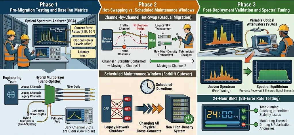
Phase 1: Pre-Migration Testing and Baseline Metrics
Before any production traffic is touched, the engineering team must establish a definitive baseline of the existing network state. This involves capturing current error rates, optical power levels, and latency metrics across the active legacy channels.
If the upgrade involves overlaying new high-density wavelengths onto an operational coarse network, a hybrid multiplexer (often called a band-splitter) must be inserted. This phase requires validating that the “dark” or unused channel slots allocated for the expansion are entirely clear of optical noise or unintended back-reflections using an Optical Spectrum Analyzer (OSA).
Phase 2: Hot-Swapping vs. Scheduled Maintenance Windows
Phase 3: Post-Deployment Validation and Spectral Tuning
Once the physical connections are completed and the lasers are active, the system requires careful spectral tuning. Because different wavelengths attenuate at slightly different rates over long distances, the optical power profile across the channel spectrum will look uneven at the receiving end.
Engineers must use variable optical attenuators to balance the power levels, ensuring that no single high-power channel saturates the receiving optics while weaker channels drop into the noise floor. After achieving spectral equilibrium, long-term bit-error rate testing (BERT) should run for a minimum of 24 hours to catch intermittent stability issues caused by thermal drifting or polarization anomalies.
Migration Strategy Comparison
The choice between a rolling, incremental deployment and a complete structural cutover hinges on an enterprise’s risk tolerance, available support personnel, and architecture layout.
| Evaluation Metric | In-Service Rolling Wavelength Migration | Full Maintenance Window Forklift Overhaul |
|---|---|---|
| Production Downtime | Near-zero; traffic is shifted incrementally channel by channel. | Defined window of total service disruption across the link. |
| Operational Risk | Moderate; unexpected spectral interactions can impact live adjacent channels. | High during the window; low once baseline validation passes. |
| Time Required | Extended; can span days or weeks depending on channel counts. | Compressed; typically executed within a single 4-to-6-hour window. |
| Personnel Allocation | Continuous monitoring required by specialized optical engineers. | All-hands-on-deck effort during the physical cutover event. |
| Rollback Complexity | Simple; reverse the patch changes for the specific troubled channel. | Complex; requires reverting the entire structural topology back to legacy states. |
Conclusion: Future-Proofing with a Seamless DWDM Implementation
Upgrading an enterprise or metro network to a high-capacity multi-channel architecture represents a profound evolutionary leap for corporate digital infrastructure. It shifts the organization away from the restrictive paradigm of physical fiber scarcity and into an environment of abundant, scalable bandwidth. By methodically auditing the physical fiber plant, selecting highly adaptable tunable optical transceivers, and executing a tightly controlled migration strategy, engineering teams can breathe new life into existing glass assets.
Ultimately, implementing DWDM solutions correctly ensures that the underlying transport layer ceases to be a limiting factor for business growth, transforming the physical network into an invisible, hyper-scalable pipeline capable of supporting technological demands for decades to come.
FAQ
Can I upgrade to a DWDM network without replacing my older dark fiber?
In the vast majority of scenarios, yes, older single-mode fiber installations can remain in place. The underlying glass medium itself is inherently capable of carrying hundreds of distinct light wavelengths simultaneously. However, older fiber runs must undergo rigorous testing to verify total link loss and polarization mode dispersion. If the old fiber exhibits high attenuation or severe physical splices, specialized coherent optical transceivers or additional inline amplification stages may need to be deployed to overcome those physical imperfections, avoiding the need to pull new physical cabling through the ground.
What is the risk of signal crosstalk during a live DWDM migration?
The primary risk of crosstalk occurs when channel spacing is incredibly narrow (such as 50 GHz grids) and the transmitting lasers experience thermal drift. If a transceiver’s internal cooling mechanism fails or fluctuates, its output wavelength can wander slightly into the spectral space allocated for an adjacent channel, causing severe data corruption and packet loss on that neighboring link. Utilizing modern, high-precision temperature-stabilized lasers and high-isolation passive multiplexers minimizes this phenomenon, ensuring that channels remain completely isolated even during highly fluid migration events.
What are the drawbacks of conventional fixed-wavelength transceivers?
Each module is hardcoded to a single ITU grid channel at manufacture. Operators have to stock dozens of distinct spare SKUs for channel failure coverage, leading to high inventory cost and cumbersome maintenance with no flexible wavelength rerouting capability.