
Pipelines, rail corridors, border fences, wellbores and seabed cables share one property: they are long, and faults anywhere along them matter. Point sensors have never solved that geometry well, because covering 50 km at 10 m spacing means thousands of devices, thousands of power feeds and a maintenance burden that scales with length. Fiber optic sensing changed the economics by making the cable itself the sensor, and among those techniques distributed acoustic sensing systems are the ones that recover a usable waveform rather than a simple alarm.
Distributed acoustic sensing works by launching short, highly coherent laser pulses into an optical fiber and measuring the phase of the light that scatters back from microscopic imperfections in the glass. Because that phase shifts whenever the fiber is stretched or compressed, an interrogator connected at one end can reconstruct strain at every few meters of a cable tens of kilometers long. Each segment becomes an independent acoustic channel, so a single instrument listens to the whole route at once, continuously.
The sections below follow that chain from scattering physics to the practical limits engineers hit in the field.
What Is Distributed Acoustic Sensing?
Distributed acoustic sensing is a measurement technique in which the sensing element is the fiber itself rather than a device attached to it. One interrogator converts an ordinary single-mode cable into a continuous array of strain sensors, with no electronics, no power supply and no maintenance along the route.
The distinction matters more than it sounds. A conventional array of 5,000 geophones at 10 m spacing along 50 km needs 5,000 housings, a power and telemetry network, and a field team to service it. The same fiber with the same spacing yields 5,000 channels from one rack-mounted instrument. Because the fiber is passive and dielectric, it is immune to electromagnetic interference and lightning, needs no ignition-risk assessment, and works where no electronics would survive. What the system actually records is not sound pressure but strain rate along the fiber axis, which is why the data is usually presented in nanostrain per second rather than decibels.
What Physical Principle Makes Distributed Acoustic Sensing Work?
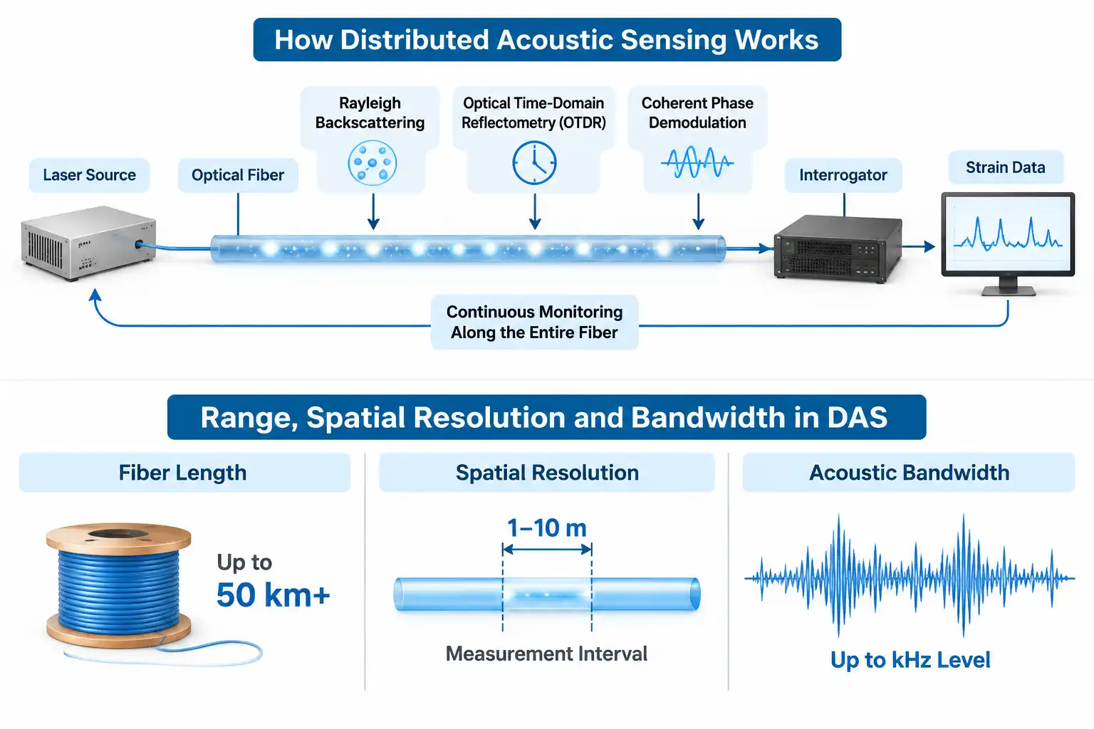
Distributed acoustic sensing relies on three mechanisms working together: Rayleigh backscattering inside the glass, optical time-domain reflectometry to establish where a given portion of backscatter originated, and coherent phase demodulation to convert tiny optical path changes into strain.
Remove any one of the three and the technique degrades: scattering without phase coherence cannot tell extension from compression, and phase measurement without time gating averages the whole cable into one number. The combination is what makes thousands of independent channels possible on one strand.
Rayleigh Backscattering Inside the Fiber
When light travels along a fiber, a small fraction is scattered backwards by refractive index fluctuations frozen into the glass during drawing. The pattern is random but stable: because the scatterers do not move, any change in the returning light comes from a change in the fiber itself. Only a tiny proportion of the pulse returns to the guided mode, so the signal arrives weak and requires coherent detection. Launch power cannot simply be increased to compensate, because above a threshold the fiber becomes nonlinear and the pulse distorts. Standard single-mode fiber guiding light near 1550 nm is the usual medium, as covered in general fiber optic reference material.
Phase-Sensitive OTDR and the Gauge Length
Classical optical time-domain reflectometry measures returning intensity against time to locate breaks and splices. Phase-sensitive OTDR keeps the source coherent and compares the phase of backscatter from two points separated by a fixed distance instead. That distance, the gauge length, is typically a few meters to a few tens of meters, and the phase difference across it is linear with strain, which is what makes quantitative measurement possible. One platform can serve both functions, an OTDR solution serving link integrity while the sensing channel handles the acoustics.
Gauge length is a design choice: a longer gauge averages more scatterers and improves signal-to-noise ratio, but it low-pass filters the channel.
How Does a DAS Interrogator Turn Backscatter into Acoustic Data?
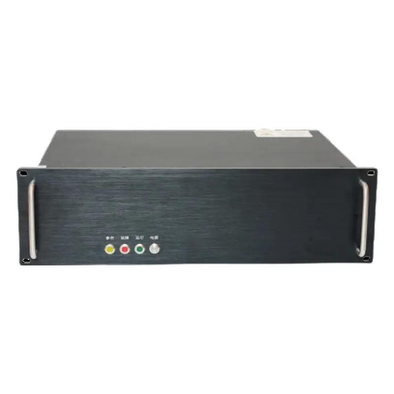
An interrogator converts backscatter into data by comparing successive phase measurements from the same fiber section, repeating it thousands of times per second for every channel along the cable. A production DAS System performs this chain in a fixed sequence.
- A narrow-linewidth laser generates continuous light, since frequency noise would otherwise appear in the output as strain.
- An acousto-optic modulator carves the light into pulses, setting pulse width and a frequency shift for heterodyne detection.
- An amplifier raises pulse energy to the limit set by stimulated Brillouin scattering.
- A circulator routes the pulse into the fiber and the backscatter into the receiver.
- A coherent receiver mixes backscatter with a local oscillator, producing in-phase and quadrature components.
- A digitizer samples the result at hundreds of megasamples per second.
- Digital signal processing gates samples into channels by time of flight, unwraps phase, differences across the gauge length, and outputs strain rate per channel.
Vendors describe these outputs inconsistently, which is why the parameter set standardized in IEEE 3101-2023 is worth using as a comparison basis.
| Parameter | What it defines | Typical range |
| Spatial resolution | Gauge length over which strain is averaged | 1 to 10 m |
| Spatial interval | Distance between consecutive channels | 0.25 to 5 m |
| Measurement range | Maximum fiber length interrogated | 40 to 100 km |
| Acoustic frequency range | Vibration band the system can resolve | Sub-hertz to 20 kHz |
| Dynamic range | Ratio of largest to smallest detectable signal | Around 100 dB |
Two systems quoting “1 m resolution” can therefore mean very different things, since one may be reporting spatial interval and the other gauge length.
How Do Range, Spatial Resolution and Bandwidth Interact?
Range, spatial resolution and bandwidth are coupled through pulse width and round-trip time, so no interrogator maximizes all three at once. Improving one costs another, so selection means ranking which property the route needs.
Spatial resolution follows directly from pulse duration: the resolution equals the speed of light in vacuum times pulse duration divided by twice the group index, so a 100 ns pulse resolves roughly 10 m in standard fiber. Bandwidth is limited separately: only one pulse can occupy the fiber at a time. The round trip for a 50 km span takes about 490 microseconds, capping the pulse repetition rate near 2 kHz and, by sampling theory, the highest unambiguous acoustic frequency near 1 kHz. Shorten the span and the ceiling rises proportionally.
| Fiber length | Round-trip time | Maximum pulse rate | Acoustic bandwidth ceiling |
| 5 km | 49 us | 20.4 kHz | 10.2 kHz |
| 10 km | 98 us | 10.2 kHz | 5.1 kHz |
| 25 km | 245 us | 4.1 kHz | 2.0 kHz |
| 50 km | 490 us | 2.04 kHz | 1.02 kHz |
How Far Can Distributed Acoustic Sensing Measure?
Without amplification, practical reach lands in the 50 to 70 km range, bounded by fiber attenuation and the nonlinear power limit. Optical amplification, using Raman or Brillouin pumping, extends reach beyond 100 km at the cost of added complexity and reduced resolution. The other lever is gauge length: a 200 m gauge over 100 km produces about 10,000 channels, a configuration suited to regional seismology but not to detecting a shovel striking a pipe. Routes that need meter-level localization accept shorter spans.
How Does Distributed Acoustic Sensing Compare with DVS, DTS and Point Sensors?
Distributed acoustic sensing demodulates optical phase to recover a waveform proportional to strain, while distributed vibration sensing reads only backscatter intensity, distributed temperature sensing measures temperature through Raman or Brillouin scattering, and point sensors report a single absolute value at one location.
The distinction between the first two is frequently blurred, and some vendor literature still lists distributed vibration sensing as an alternative name for distributed acoustic sensing. It is not. Both share the phase-sensitive OTDR platform, but an intensity-based system locates a disturbance without producing a response proportional to its magnitude, and without phase coherence it cannot tell extension from compression. That limitation is stated plainly in a U.S. Bureau of Reclamation assessment of DAS, and it is the reason a DVS Distributed Vibration Sensing unit remains the cheaper answer when the requirement is an alert rather than a waveform.
| Technique | Measured quantity | Spatial resolution | Typical role |
| DAS | Optical phase, strain rate | 1 to 10 m | Broadband acoustic monitoring and classification |
| DVS | Backscatter intensity | 5 to 10 m | Intrusion alerts at lower cost |
| DTS | Temperature | 1 to 5 m | Leak, seepage and fire detection |
| Point sensor | Absolute value at one point | One point only | Reference, calibration, verification |
What Fiber and Installation Conditions Does DAS Require?
Standard single-mode fiber is sufficient, but sensitivity depends on how firmly the cable is coupled to the medium being monitored. A fiber that can move independently of the ground or pipe records the motion of the cable, not the motion of the asset.
Most disappointing deployments trace back to coupling rather than to the interrogator. Five factors decide the outcome:
- Cable construction. Tight-buffered cable transmits strain efficiently; loose-tube cable decouples the fiber from the sheath, suiting temperature work but weak for acoustics.
- Installation method. Direct burial in native soil couples best. Concrete duct and aerial stringing both attenuate high frequencies.
- Backscatter-enhanced fiber. Engineered fiber with higher scattering raises signal-to-noise ratio on long or low-coupling routes, at higher cable cost.
- Loss budget. Every connector and splice adds loss and reflection, so a sensing link needs a designed budget rather than an improvised one.
- Environment. Downhole and subsea routes need cable rated for the temperature and pressure involved, and the fiber’s coating affects long-term hydrogen-induced attenuation.
Where Is Distributed Acoustic Sensing Applied?
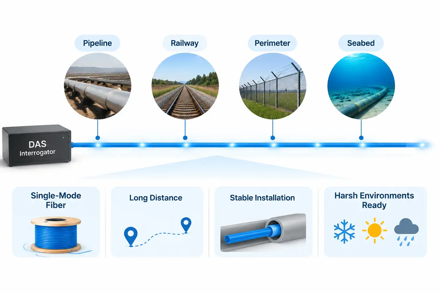
Distributed acoustic sensing is applied wherever a long, narrow asset or a large area needs continuous listening: pipelines, perimeters, rail and road corridors, wellbores, subsea cables, dams and the ground itself.
- Pipeline integrity. Third-party excavation, leak noise and pig passage are all detectable from a fiber in the same trench, with location good enough to dispatch a patrol.
- Perimeter and border security. Footsteps, fence cutting and vehicle traffic produce distinguishable signatures across tens of kilometers; classification separates a usable system from an alarm generator.
- Rail and road corridors. Train passage, axle faults, rockfall and traffic counts come from cable already installed for signaling or telecom.
- Seismology and ground imaging. Unused telecom fiber becomes a dense array for earthquake detection and ambient noise tomography, the application that has driven most academic adoption.
- Carbon storage and geothermal. Well integrity, fracture growth and plume movement are monitored with the same fiber used for completion.
- Subsea and offshore. Anchor drag, cable faults and marine mammal vocalizations are recorded along cables not installed for sensing at all.
- Dams, levees and slopes. Seepage and internal erosion generate broadband noise that precedes visible failure by a useful margin.
What Limits DAS Performance in the Field?
Most field limits come from the statistics of backscatter, cross-sensitivity between strain and temperature, and the volume of data produced, rather than from the optical hardware itself.
- Fading. Because backscatter is a random interference pattern, some sections return almost no light and yield unusable phase. Multi-frequency probing and channel diversity mitigate it; no single-frequency system eliminates it.
- Cross-sensitivity. Temperature change alters optical path length exactly as strain does, so a thermal transient can masquerade as ground motion. Reference sections, decoupled fiber or independent temperature measurement resolve it.
- Axial sensitivity only. A wave arriving broadside to the fiber produces little axial strain, so route geometry must match the wavefield being sought.
- Data volume. Thousands of channels at kilohertz rates generate tens of gigabytes per hour per interrogator, so edge processing becomes a design requirement.
- Calibration. The output is relative strain rate, so converting it to acceleration or displacement needs site-specific transfer functions from reference sensors.
FAQ
Three questions come up once the principle and the hardware are settled.
How Much Does a Distributed Acoustic Sensing System Cost to Deploy?
Cost is dominated by the interrogator and the installation, not by the fiber. Interrogator capital scales with channel count, reach and bandwidth, and a long route on existing dark fiber carries almost no cable cost, which is why per-kilometer figures fall sharply with route length. Budget separately for storage and processing, since data handling often exceeds hardware cost over five years.
Can DAS Share a Live Telecom Fiber Without Disrupting Traffic?
Sensing needs its own strand, but it runs comfortably inside the same cable as live traffic on a spare fiber or unused tube, the standard arrangement for telecom-hosted deployments. Sharing one strand with active traffic is not practical, because the sensing pulse occupies the entire fiber and would interfere with the data channels it is meant to coexist with.
How Is DAS Data Turned into Alarms Rather than Raw Noise?
Raw channels are band-pass filtered, stacked across neighboring channels, and passed through classifiers trained on site-specific signatures. Alarm logic then applies thresholds with dwell time so a single transient does not trigger a response. The engineering effort sits in the classifier and the site survey, which is why two installations with identical interrogators can perform very differently.