
AI training and inference no longer fit inside a single building. Power density, cooling limits and land constraints push operators to spread GPU clusters across several data halls, campuses and metro sites, which turns the fiber between those facilities into part of the compute fabric itself. Metro data center interconnect (DCI) is the layer that binds these sites together, and it is now planned with the same rigor as servers and switches, because a bottleneck or a fiber cut between two AI facilities directly degrades model training throughput and service availability.
Planning metro DCI for AI infrastructure comes down to three coordinated decisions: size capacity against peak and failure-state traffic rather than average utilization, budget latency from the physical distance of fiber at roughly 5 microseconds per kilometer each way, and verify resilience down to the physical route rather than trusting logical redundancy. Get these three variables right, and multiple data centers behave as one high-performance facility.
The sections below examine each of these planning dimensions in turn, starting with what metro DCI actually covers and how AI workloads changed its requirements.
What Is Data Center Interconnect (DCI)?
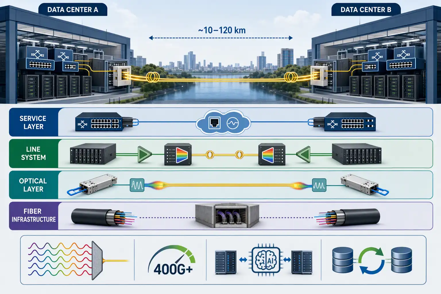
Data center interconnect is the set of high-bandwidth optical links and transport equipment that connects two or more data centers so they can exchange workloads, datasets, backups and replicated state as if they were one resource pool. For AI infrastructure, DCI typically means coherent optical transmission over metro distances of roughly 10 to 120 km, where tightly coupled GPU workloads can still be synchronized.
A Data Center Interconnect link is built as a stack of layers: single-mode fiber in duct routes, coherent or direct-detect optics that light the fiber, a line system with amplifiers and multiplexers, and a service layer that presents Ethernet or wavelength services to switches and routers. Most operators own only some of these layers, and every planning decision depends on which layers sit inside your own control. Because inter-site links must carry far more traffic than ordinary enterprise wide-area connections, they rely on dense wavelength division multiplexing and coherent transmission to move 400G and higher per wavelength over a single fiber pair, as described in the Wikipedia overview of DCI.
Metro DCI vs Campus and Long-Haul Links
Distance determines which technology tier fits, and misjudging it either wastes budget or breaks performance.
| Link Scope | Typical Distance | Common Optics | Typical AI Traffic |
| Campus | 0.5 to 10 km | Direct-detect PAM4 modules | Scale-up fabric, data hall to data hall |
| Metro DCI | 10 to 120 km | Coherent 400G ZR-class pluggables | Synchronous training, replication |
| Regional or long-haul | 120 to 1000+ km | Coherent ZR+ and embedded transponders | Checkpoint transfer, dataset migration |
Metro DCI occupies the critical middle ground: far enough that direct-detect optics cannot reach, yet close enough that round-trip latency stays inside the budgets required by synchronous replication and tightly synchronized GPU communication.
What Is Scale Across, and Why Does AI Need It?
Scale across is an architecture that extends a coordinated AI fabric across multiple data centers, so inter-site network behavior becomes part of workload performance rather than a background transport concern. It emerged because single buildings can no longer supply the power and space that gigawatt-scale AI clusters demand.
The three scaling directions answer different constraints. Scale-up increases compute within a rack or supernode over short copper and optics links. Scale-out spreads a cluster across data hall floors within a site. Scale across links multiple buildings or metro sites into one logical training cluster, carrying collective GPU communication, gradients and checkpoints between facilities. When a campus cannot draw enough power for a full GPU fleet, operators split it across sites and use metro DCI to make the split nearly invisible to the training job.
Two forces make this the default growth path. First, demand itself is exploding: the International Energy Agency projects global data center electricity consumption roughly doubling from 485 TWh in 2025 to about 950 TWh by 2030, with AI-focused facilities growing fastest, in its Energy and AI report. Second, distributed AI traffic is far heavier than traditional inter-center flows. Aggregate bandwidth between two large AI sites can reach an order of magnitude beyond a conventional DCI baseline, with inter-site link counts in the thousands of coherent ports rather than the hundreds. Capacity, latency and resilience planning must therefore be done together, which is where the next three sections begin.
How Is Capacity Planning Performed for Metro DCI?
Capacity planning for metro DCI is performed by modeling each inter-site traffic type separately, sizing the link for peak and failure-state load rather than average utilization, then mapping that demand onto wavelengths and fiber pairs with headroom for the next speed generation. Planning around averages is the single most common cause of congestion on AI interconnects.
AI workloads differ sharply in how they stress a link, so a useful model separates them before adding anything up.
| AI Traffic Type | Bandwidth Demand | Latency Sensitivity | Failure Impact |
| Synchronous GPU training communication | Very high, bursty | Very high, microseconds to milliseconds | Training stalls or degrades |
| Model checkpoint transfer | High, bulk | Low, tolerates tens of milliseconds | Recovery delayed |
| Dataset replication and distribution | High, sustained | Low | Slows onboarding of new sites |
| Storage replication for disaster recovery | Moderate | Deterministic, often under 2 ms RTT | Data loss window widens |
| Inference distribution | Moderate | Regional latency targets | User-visible slowdown |
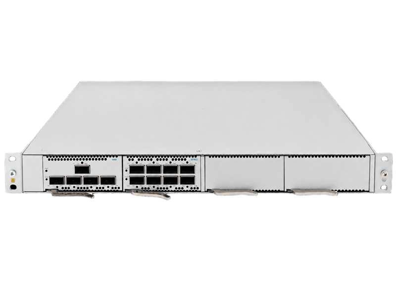
A disciplined planning process for an Optical DCI Networks Solution Series style deployment follows five steps:
- Inventory inter-site flows by workload, including growth projections from planned GPU expansions.
- Convert flows into peak aggregate demand, then add a failure-state case where one link or site absorbs another’s traffic.
- Map demand onto wavelengths, checking fiber count, amplifier spacing and available spectrum on the chosen routes.
- Validate power, rack space and cooling at both endpoints for the planned optics and line equipment.
- Reserve upgrade headroom, both spare fiber pairs and unlit spectrum, so moving from 400G to 800G per wavelength is a card swap rather than a construction project.
This last point matters more than it first appears. Replacing endpoint optics is cheap; acquiring new duct space in a congested metro corridor years later often is not, and the delay directly postpones AI capacity expansion.
How to Plan Latency in Metro DCI
Latency in metro DCI is governed by physics: light in standard single-mode fiber propagates at roughly 5 microseconds per kilometer in each direction, so round-trip delay is set by route distance and cannot be reduced by adding bandwidth. Planning means allocating a latency budget across fiber distance, optics, switching and application tolerance, then choosing site locations and routes that fit inside it.
The fiber floor alone produces the following round-trip values, before any equipment adds delay.
| One-Way Fiber Route | Fiber-Only Round Trip | With Equipment and Routing Overhead |
| 10 km | About 0.1 ms | Roughly 0.15 to 0.25 ms |
| 40 km | About 0.4 ms | Roughly 0.5 to 0.7 ms |
| 80 km | About 0.8 ms | Roughly 0.9 to 1.2 ms |
| 120 km | About 1.2 ms | Roughly 1.4 to 1.8 ms |
These numbers look small until a budget is imposed on top of them. Synchronous storage replication generally requires round-trip latency in the low single-digit milliseconds, which is why metro DCI for synchronous workloads is a story told in the 40 to 100 km range: beyond that, the fiber floor alone consumes most of the budget. Real routes add cable slack at splice points, patch panels, amplifier sites and switching hops, which nudges the effective distance upward. Distance also interacts with buffering. On a high-speed inter-site link spanning tens of kilometers, a large volume of data is already in flight before congestion feedback returns to the sender, so endpoints need the buffering and traffic management to absorb bursts rather than drop and retransmit them. When a route cannot meet the budget, the fixes are architectural, not optical: move the workload closer, or switch the traffic class to asynchronous replication and checkpoint transfer that tolerate delay.
How to Build Resilience into Metro DCI
Resilience in metro DCI is built by verifying physical route diversity, protecting the optical line so failover happens in milliseconds rather than minutes, and monitoring the fiber plant continuously so faults are located and repaired before they cascade. Logical redundancy on paper is not resilience.
The most expensive trap in DCI planning is confusing circuit diversity with path diversity. Two circuits sold by two different providers can share the same trench, bridge crossing or utility corridor for part of their route, and a single backhoe cut then takes both down at once. The same applies to building entrances: two fiber entries that converge into one duct a block away provide no protection against that duct failing. Genuine route diversity has to be validated with route documentation from the fiber provider, covering the full physical path of every circuit, and confirmed by separate entrances, separate splice points and, ideally, separate amplifier sites on the two paths.
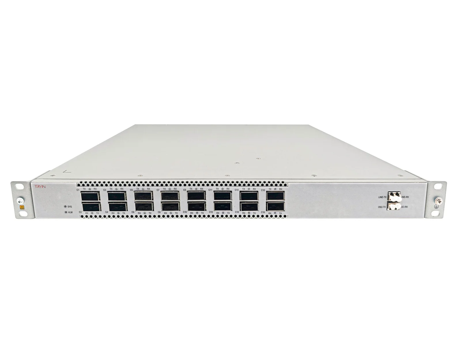
Once routes are physically independent, protection mechanisms can actually deliver on their promises. Line-level protection such as 1+1 optical protection switches traffic to a diverse path within milliseconds. Site-level design spreads critical functions across facilities so no single site failure stops the training job or the service. Fiber-level visibility rounds out the picture: continuous monitoring of the live fiber plant with fault localization to the meter level turns an hours-long hunt for a break into a direct dispatch, which is a core capability of a Zero-Touch DCI Network Series deployment, where automated protection and real-time telemetry remove manual intervention from the recovery path.
Resilience planning closes the loop with the other two dimensions. A protection path is longer than the primary path, so its latency must also fit the budget, and failure-state traffic concentration must fit the capacity plan. Capacity, latency and resilience are three views of one design, and each one should be re-verified whenever any of the others changes.
Frequently Asked Questions
How does metro DCI planning differ from long-haul DCI planning?
Metro DCI is optimized for tightly coupled workloads: latency budgets measured in single-digit milliseconds, coherent pluggables in router or switch ports, and single amplified spans. Long-haul DCI instead carries latency-tolerant traffic such as dataset migration, checkpoints and backups, and it uses ROADM line systems with multiple amplified spans and regeneration planning. The planning metrics that dominate are different: round-trip time and route diversity for metro, and spectrum, attenuation and repair accessibility for long-haul.
Should AI metro DCI be built on dark fiber or managed wavelength services?
Dark fiber suits operators with optical engineering expertise and sustained traffic growth, because monthly cost stays roughly flat as wavelengths are added, and it grants full control over the line system, monitoring and upgrade timing. Managed wavelength services reduce operational burden and shift maintenance responsibility to the provider, at the cost of less route visibility and dependence on the provider’s upgrade cycle. High-growth AI campuses with predictable multi-year expansion usually favor dark fiber, while enterprises with a handful of stable links often start with managed services.
What role do 400G and 800G coherent optics play in metro DCI?
Coherent pluggables in the 400G ZR class make metro DCI economical by putting the transponder function directly into router and switch ports, which removes standalone transponder racks, reduces power per bit and shortens deployment. They carry 400G or 800G per wavelength over amplified metro spans of up to roughly 120 km. Their main planning implication is that capacity upgrades become largely a matter of swapping pluggable modules, provided the fiber and spectrum headroom was reserved in the original capacity plan.