
Data center traffic is growing faster than the fiber infrastructure that carries it. AI training clusters, cloud replication, and content delivery are pushing inter-data-center bandwidth into the terabit range, while dark fiber leases and new cable deployments remain expensive and slow to provision. For network teams, the question is no longer whether to densify their optical links, but how to select the right dense wavelength division multiplexing platform for their specific environment.
To choose the right DWDM system for a data center, evaluate six dimensions in order: architecture (passive or active), channel capacity, transmission reach, transceiver technology, scalability, and total cost of ownership. Match the architecture to your distance and power constraints, size the channel count against a five-year traffic forecast, and select transceivers, direct detect for shorter spans and coherent optics for metro and regional links, that align with your link budget. A well-chosen DWDM system scales capacity on existing fiber without disruptive redesign.
The sections below walk through each of these dimensions in detail, compare DWDM with CWDM, and close with a step-by-step selection process you can apply directly to your own network plan.
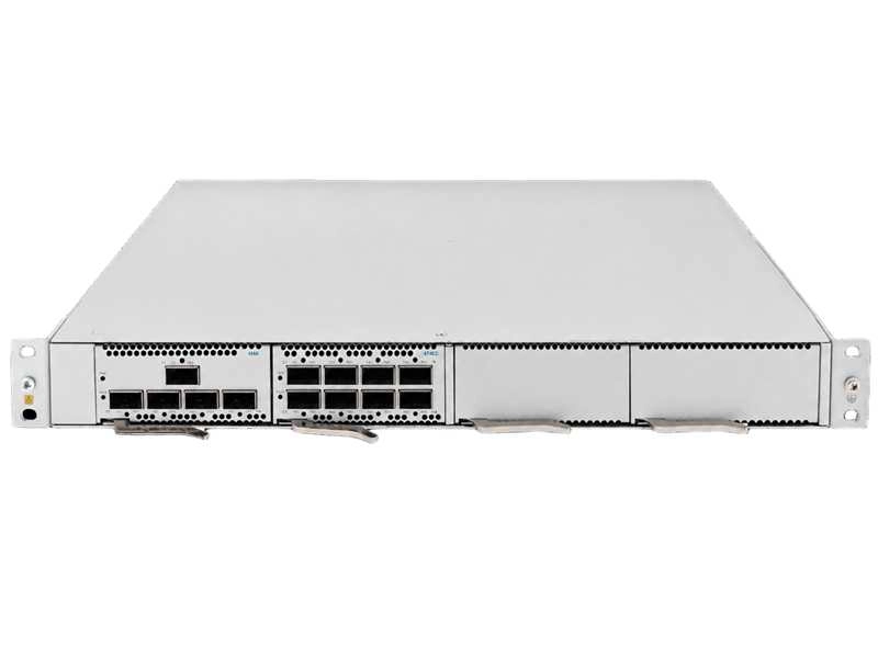
What Is a DWDM System in a Data Center Context?
A DWDM system is an optical transport platform that combines many tightly spaced wavelengths onto a single fiber pair, allowing a data center to multiply link capacity without laying new fiber. Each wavelength carries an independent data stream, so one fiber can transport dozens of parallel 100G, 400G, or 800G channels.
DWDM places wavelengths in the C-band around 1550 nm, the region where fiber attenuation is lowest, with channel spacing of 100 GHz or 50 GHz as defined by the ITU-T G.694.1 spectral grid standard. At 100 GHz spacing a system typically supports about 40 to 48 channels; at 50 GHz, interleaving can push the count to 80 or 96 channels on a single fiber pair.
Inside the data center, a DWDM system most often serves DWDM for Data Center Interconnect links between campus buildings, metro data centers, and regional availability zones. It is also increasingly used for AI cluster scale-across traffic, where GPU pods in separate facilities need high-bandwidth, low-latency paths that cannot be served by additional fiber alone.
Passive vs Active DWDM: Which Architecture Fits Your Data Center?
Choose a passive DWDM system for short, stable point-to-point links where the DWDM transceivers plug directly into your switches; choose an active DWDM system when distances exceed roughly 80 km, traffic is dynamic, or you need amplification, protection switching, and centralized management.
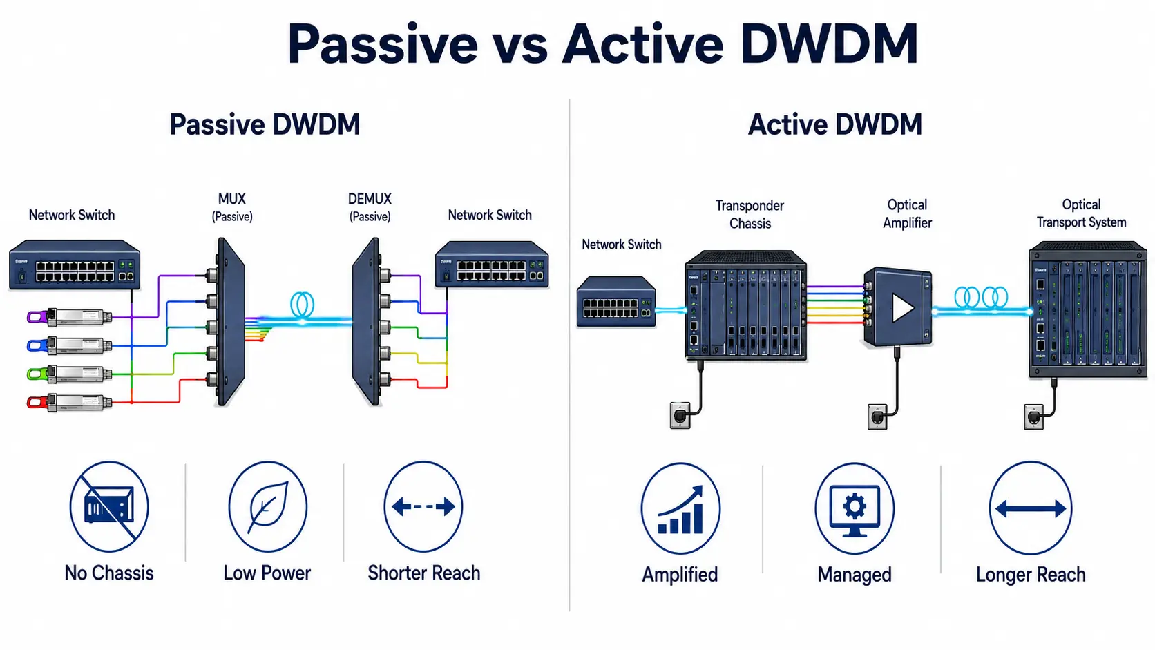
In a passive system, colored DWDM optics reside in the switch ports and connect to an unpowered multiplexer. There is no separate transport chassis, which keeps cost, power draw, and operational complexity low. The trade-off is limited reach and no built-in monitoring beyond what the transceivers themselves report.
An active system uses a standalone Optical Transport Systems platform with transponders, amplifiers, and add-drop capability. It converts short-reach switch outputs into long-haul DWDM signals and supports optical power monitoring, protection schemes, and remote provisioning.
| Attribute | Passive DWDM | Active DWDM |
| Power required | None for multiplexing | Chassis and amplifier power |
| Typical reach | Up to about 80 km unamplified | Hundreds of km with amplification |
| Capital cost | Low | Higher |
| Management visibility | Limited to transceiver telemetry | Full optical layer monitoring |
| Best fit | Campus and metro point-to-point | Regional, multi-service, growing networks |
Topology follows the architecture decision. Point-to-point links suit stable data center pairs, while ring or hub-and-spoke designs add failover redundancy for sites carrying mixed traffic.
Key Factors to Consider When Choosing a DWDM System
The main selection factors are channel capacity, transmission reach, transceiver and modulation technology, and the ability to scale and manage the system as traffic grows. Each factor constrains the others, so they should be evaluated together rather than in isolation.
Capacity and Channel Count
Size the channel count against current demand plus a five-year growth forecast, not just today’s traffic. Common configurations include:
- 8 to 16 channels for enterprise and campus interconnects
- 40 to 48 channels for metro networks and data center interconnection
- 80 to 96 channels for carrier backbones and hyperscale builds
Narrower 50 GHz spacing doubles channel density but demands tighter wavelength stability from the optics and higher filter quality in the multiplexers. If your growth curve is steep, a platform that supports a future move to 50 GHz, or to flexible-grid spectrum allocation, protects the original investment.
Beyond the raw channel count, the wavelength plan itself deserves attention. Guard bands between wavelength groups reduce crosstalk risk and make future channel additions simpler, while grouping services with similar protection or latency requirements onto adjacent wavelengths keeps day-to-day troubleshooting manageable. Align the central frequency plan with your transceiver tuning range so that spare optics can be deployed on any channel without re-engineering the filter layout.
Transmission Reach and Optical Power Budget
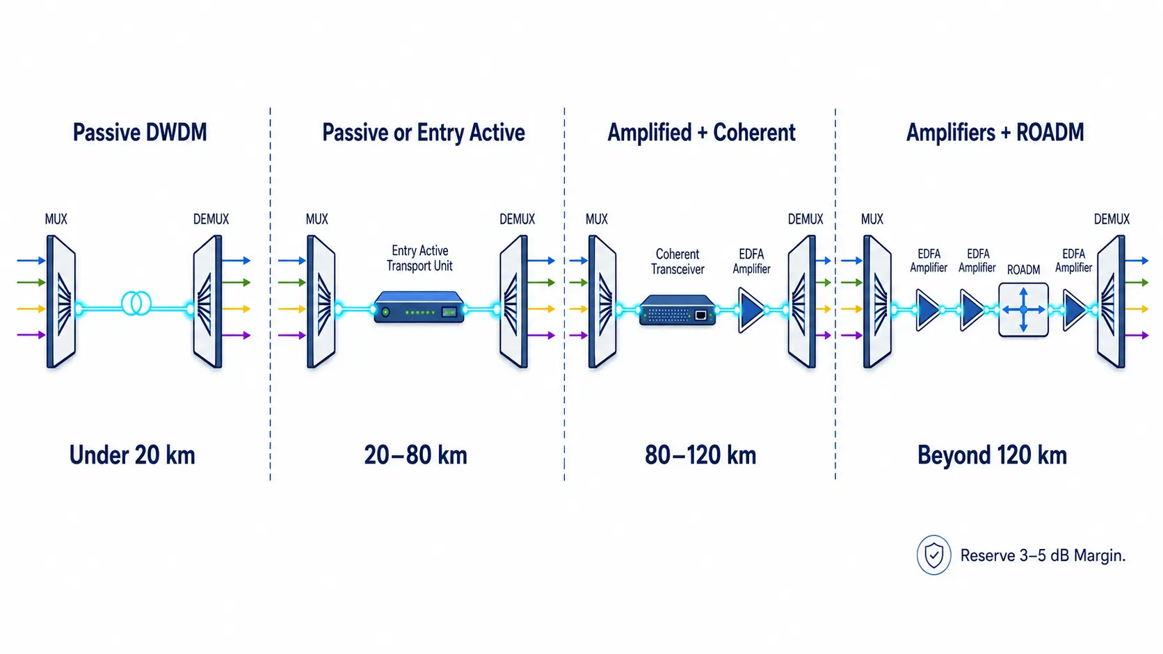
Reach determines whether amplification is needed and how much link margin to reserve. A practical distance ladder looks like this:
| Distance | Typical approach |
| Under 20 km | Unamplified, passive multiplexing |
| 20 to 80 km | Passive DWDM or entry active system |
| 80 to 120 km | Amplified spans, coherent optics |
| Beyond 120 km | Multi-stage amplification, ROADM line systems |
The optical power budget must account for fiber attenuation of roughly 0.25 to 0.35 dB per km, insertion loss from mux/demux filters and connectors, and a safety margin of 3 to 5 dB for component aging and maintenance. Underestimating the budget is one of the most common causes of commissioning failures.
Reach is not only a power question. At higher data rates, chromatic dispersion, polarization mode dispersion, and nonlinear effects start to limit span length before raw attenuation does. For amplified links, the optical signal-to-noise ratio becomes the governing metric, and coherent receivers with digital signal processing tolerate much lower OSNR than direct detect modules. A span that passes a power budget check on paper can still fail acceptance if dispersion or OSNR was never modeled, so both calculations belong in the design phase.
DWDM Transceivers and Coherent Optics
Transceiver choice sets the per-wavelength payload and the reach envelope. Direct detect modules such as 10G and 25G DWDM SFP parts are economical for shorter spans. Above 100G per wavelength, coherent optics dominate: they modulate both amplitude and phase, achieving far higher spectral efficiency over metro and regional distances.
Pluggable coherent modules built to the OIF 400ZR and OpenZR+ agreements bring 400G wavelengths directly into standard switch ports, with 400ZR targeting point-to-point DCI up to roughly 120 km and OpenZR+ extending to amplified and ROADM-based networks. For data centers, pluggable coherent optics remove an entire layer of transponder equipment on many links.
When selecting optics, verify the data rate, form factor compatibility with your switching hardware, transmitter power, and receiver sensitivity against the link budget, and confirm that the module wavelengths match the channel plan of your multiplexers.
Scalability and Management
A DWDM system should grow by adding wavelengths, not by replacing hardware. Look for platforms that let you light new channels incrementally, reserve spectrum for future use, and integrate optical-layer telemetry into your existing monitoring. Real-time visibility of per-wavelength optical power, alarm thresholds, and fault location, including OTDR-based fiber diagnostics, shortens mean time to repair and prevents silent degradation.
DWDM or CWDM: Which Should a Data Center Choose?
Choose DWDM when you need more than 18 channels, reach beyond about 80 km, or a clear path to 400G and beyond; choose CWDM for short, low-capacity links where cost and simplicity outweigh scalability.
| Parameter | CWDM | DWDM |
| Channel spacing | 20 nm | 0.8 nm |
| Channel count | Up to 18 | Up to 160 |
| Reach without amplification | Typically under 80 km | Thousands of km with amplification |
| Cost | Lower | Higher but gradually falling |
| Best fit | Access, campus, modest DCI | High-capacity DCI, metro, backbone |
The gap has narrowed in recent years, and DWDM now delivers better long-term value in most greenfield data center builds because it supports higher speeds and future upgrades on the same fiber. For a deeper comparison of the two technologies, see the guide CWDM vs DWDM, which covers the trade-offs in detail.
Total Cost of Ownership and Power Efficiency
Evaluate a DWDM system on cost per Gbps over its full lifecycle, including power, cooling, rack space, and expansion modules, rather than on the initial price of the chassis and multiplexers.
A passive system has a small footprint and near-zero incremental power, which matters in facilities where every rack kilowatt is spoken for. Active platforms carry higher operating expense but amortize shared amplification across many wavelengths, so cost per bit drops as the system fills. When comparing vendors, ask for the power draw per 400G wavelength at a typical fill level, the pricing and lead times of add-on channel cards, and the availability of spares over the expected service life. High channel density also reduces floor space per terabit, an often-overlooked line in the TCO calculation.
Interoperability is another cost lever. Open line systems and standardized pluggable optics let you source transceivers and multiplexers from different vendors, which keeps refresh pricing competitive and avoids lock-in when a platform generation changes. Confirm that any proprietary management interface you adopt can export the telemetry your operations team already uses, because retrofitting visibility tools after deployment is far more expensive than specifying them up front.
Step-by-Step Process for Choosing a DWDM System
Follow a structured sequence from traffic assessment to acceptance testing; skipping the fiber audit and link budget steps is where most selection mistakes occur.
- Baseline current traffic and build a five-year capacity forecast per route.
- Audit the fiber plant: measure span loss, connector quality, and available fiber pairs.
- Select passive or active architecture based on reach, power, and management needs.
- Design the wavelength plan, reserving channels and spectrum for growth.
- Choose transceivers and modulation formats that fit the link budget at each data rate.
- Validate the design with acceptance testing covering optical power, signal quality, and error performance before carrying production traffic.
For larger multi-site designs, also consider where reconfigurable add-drop nodes fit; an overview of ROADM in DWDM explains how ROADM-enabled systems let you reroute wavelengths remotely as traffic patterns shift.
FAQ
Is DWDM cost-effective for data center interconnect compared to leasing more fiber?
Yes, in most high-bandwidth scenarios. A single DWDM system can multiply the capacity of an existing fiber pair by 40 to 96 times, so the cost per Gbps drops sharply once you light more than a handful of wavelengths. Leasing additional fiber pairs usually only wins when total demand is low and stable, or when DWDM deployment is not operationally feasible.
Can a DWDM system be upgraded without replacing the existing fiber?
Yes. Because DWDM adds capacity in the spectral domain, upgrades happen by lighting new wavelengths, swapping in higher-rate transceivers, or tightening channel spacing, all on the same fiber plant. The main prerequisites are sufficient link margin and a channel plan that reserved room for growth.
What is the typical power consumption difference between passive and active DWDM systems?
A passive point-to-point system consumes essentially no extra power beyond the transceivers already seated in the switches, since the multiplexers are unpowered. An active platform adds chassis, control cards, and optical amplifiers, typically tens to a few hundred watts depending on span count, which is why power budgeting belongs early in the selection process rather than after deployment.