
As video, cloud, and AI-driven traffic pushes fiber networks toward their capacity limits, operators need ways to multiply throughput without laying new cable. Dense Wavelength Division Multiplexing (DWDM) transmits dozens of tightly spaced wavelength channels over one fiber pair, and the building blocks inside the system determine whether you get a modest point-to-point link or an 80-channel platform. The choice often starts with comparing CWDM vs DWDM options.
A complete DWDM system is built from five main component types: DWDM transceivers and transponders convert client signals onto precise ITU-grid wavelengths; MUX and DEMUX filters combine and separate those wavelengths; optical amplifiers like EDFA and Raman units boost all channels simultaneously; OADM and ROADM nodes add or drop selected wavelengths at intermediate points; and supporting components such as DCM, OCM, and OLP handle dispersion compensation, performance monitoring, and line protection. Each type solves a distinct problem in the optical signal path.
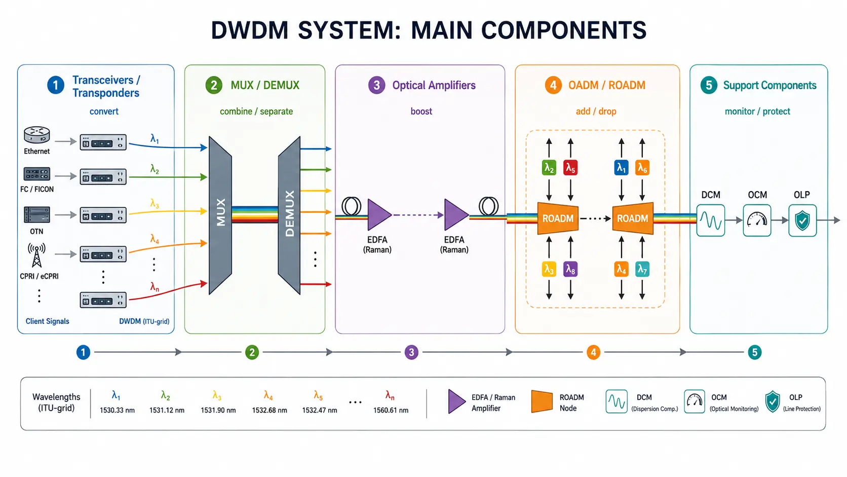
The sections below explain what each component type does, how it works, and where it fits in different network designs.
How DWDM Components Work Together
Every DWDM component occupies a defined position along an optical signal chain: client traffic is converted into wavelength channels, combined onto one fiber, boosted along the line, and finally separated back into individual channels at the far end.
A typical transmission path unfolds in the following sequence:
- A client device such as a router hands off a standard grey optical signal.
- A transceiver or transponder converts it to a wavelength locked to the DWDM grid.
- The multiplexer combines all wavelength channels into one composite signal, and a booster amplifier launches it into the fiber.
- Inline amplifiers and OADM nodes restore power and manage add/drop traffic.
- A pre-amplifier lifts the signal before the demultiplexer separates the channels, and receivers convert each wavelength back to its client signal.
DWDM components divide into active and passive categories, and the balance between the two shapes both cost and reach:
| Category | Examples | External Power | Primary Role |
| Active | Transponders, EDFAs, ROADMs, optical monitors | Required | Wavelength conversion, amplification, remote reconfiguration |
| Passive | MUX/DEMUX filters, fixed OADMs, DCMs | Not required | Combining, filtering, dispersion compensation |
Passive designs suit short, cost-sensitive links, while active platforms provide the management and reach that carrier-grade optical transport systems demand.
DWDM Transceivers and Transponders
Transceivers and transponders form the interface between client equipment and the DWDM optical layer, translating ordinary data signals into precisely tuned wavelength channels.
DWDM Transceivers
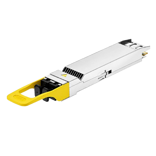
A DWDM transceiver performs the electrical-to-optical conversion while emitting at an exact channel wavelength. Because neighboring channels sit only 0.8 nm (100 GHz) or 0.4 nm (50 GHz) apart, these modules rely on wavelength-stabilized lasers with active temperature control to hold their assigned frequency. Common rates span 10G to 100G, and DWDM transceiver modules come in standard SFP, SFP+, and QSFP28 form factors that plug directly into existing switch ports.
Transponders and Muxponders
A transponder uses optical-electrical-optical (O-E-O) conversion: it receives the client’s grey signal, converts it to electrical form, performs 2R or 3R (reamplify, reshape, retime) processing, and retransmits it on an ITU-compliant wavelength. A muxponder aggregates several lower-rate client signals onto one high-speed wavelength to improve fiber utilization. At higher rates, 100G transceivers and coherent designs take over: a modern coherent optical module encodes data in both amplitude and phase, using digital signal processing to compensate fiber impairments electrically.
DWDM MUX and DEMUX Filters
The multiplexer merges individual wavelength channels into one composite signal, while the demultiplexer separates them at the receiving end, both working entirely in the optical domain.
These passive filter assemblies require no external power and little maintenance. Low channel counts typically use thin-film filters (TFF) in series, while higher counts rely on arrayed waveguide gratings (AWG), which route all wavelengths in parallel and keep insertion loss manageable beyond 16 channels.
Channel frequencies follow the ITU-T G.694.1 spectral grid, and most systems operate in the C-band between 1530 and 1565 nm, where fiber attenuation is lowest and EDFA gain is available:
| Channel spacing | Approximate wavelength spacing | Typical C-band channel count |
| 200 GHz | 1.6 nm | About 20 |
| 100 GHz | 0.8 nm | 40 to 44 |
| 50 GHz | 0.4 nm | 80 to 88 |
Insertion loss rises with channel count, from roughly 2 dB on small units to 5 dB or more on high-density modules, so channel count and link budget must be planned together.
Optical Amplifiers: EDFA and Raman
Optical amplifiers restore signal power across every channel at once, without electrical conversion, and they largely determine how far a DWDM link can reach.
The erbium-doped fiber amplifier (EDFA) is the workhorse of DWDM transport. Pump light at 980 nm or around 1480 nm excites erbium ions in a short section of doped fiber, which then amplify passing signals in the 1530–1565 nm band through stimulated emission, as explained in the RP Photonics Encyclopedia. One EDFA covers the whole C-band, so it amplifies every channel simultaneously.
Amplifiers appear at three points in a link:
- Booster amplifier, placed right after the mux to maximize launch power
- Inline amplifiers, spaced at roughly 80 to 100 km along the route
- Pre-amplifier, placed just before the demux to lift weak incoming signals
For ultra-long-haul systems, Raman amplification uses the transmission fiber itself as the gain medium, improving OSNR and extending reach.
OADM and ROADM
An optical add/drop multiplexer allows selected wavelengths to be removed or inserted at an intermediate node while all other channels pass through untouched.
Where a MUX/DEMUX pair sits only at the ends of a link, an OADM works mid-span, enabling ring and chain topologies. A fixed OADM is a passive device whose add/drop wavelengths are set at installation, while its reconfigurable counterpart, the ROADM, lets operators add, drop, or pass through any wavelength remotely, as covered in the guide to ROADM in DWDM networks.
Supporting Components: DCM, OCM, and OLP
Supporting components keep signal quality and service availability within specification once the main building blocks are in place.
- Dispersion Compensation Module (DCM): corrects the chromatic dispersion that accumulates on 10G and faster signals over long spans
- Optical Channel Monitor (OCM): measures per-channel power and OSNR in real time, feeding data to the management system
- Optical Line Protection (OLP): switches traffic to a backup fiber automatically when the primary path fails
Choosing the Right DWDM Components
The right component mix depends mainly on span length, channel count, and how much remote management the network requires.
| Application | Typical component mix | Design driver |
| Metro point-to-point | DWDM transceivers plus passive MUX/DEMUX | Low cost over short spans, no amplification needed |
| Long-haul backbone | Transponders, EDFA/Raman, DCM, ROADM | OSNR, dispersion, remote reconfigurability |
| Data center interconnect | Coherent transceivers or muxponders plus amplifiers | Maximum capacity over 40 to 120 km spans |
Capacity demands differ sharply between these scenarios. A guide to DWDM for data center interconnect shows how compact amplified platforms serve metro DCI links, while operators with legacy infrastructure can upgrade existing network with DWDM capacity simply by adding transceivers and passive filters at both ends.
FAQ
What is the difference between CWDM and DWDM components?
CWDM components use uncooled lasers and wide 20 nm filters, supporting up to 18 channels without amplification. DWDM components use temperature-stabilized lasers, narrowband filters, and optical amplifiers, which cost more but deliver far higher channel counts and reach.
How many channels can a DWDM system carry on one fiber?
A C-band system with 100 GHz spacing typically carries 40 to 48 channels, and 50 GHz spacing roughly doubles that. Extending into the L-band or using flex-grid coherent technology pushes capacity further.
When does a DWDM link need dispersion compensation?
Links running 10G and above over spans longer than about 80 km generally need chromatic dispersion management, traditionally provided by DCMs. Coherent transceivers at 100G and above compensate dispersion electronically through DSP, often removing the need for separate modules.