
As fiber optic networks expand into data centers, 5G backhaul, and fiber-to-the-home deployments, verifying the performance of every installed link has become a core part of network engineering. Fiber carries enormous traffic over hair-thin glass, and a single contaminated connector or a poor splice can degrade an entire link. Two instruments dominate field testing: the OLTS (optical loss test set) and the OTDR (optical time domain reflectometer). Many technicians, project managers, and network owners are unsure what each tool actually measures and when it should be used.
The main difference is that an OLTS measures the total end-to-end insertion loss of a fiber link using a light source at one end and a power meter at the other, giving an accurate pass or fail result, while an OTDR characterizes the link from one end by launching pulsed light and analyzing the light scattered back, revealing the location and loss of every connector, splice, and fault along the span. An OLTS tells you whether a link passes; an OTDR tells you where it fails and why. The two methods are complementary rather than competing, and structured cabling standards treat them as two tiers of a complete testing strategy.
The sections below explain how each test works, how the methods differ, and how to decide which one your project needs.
What Is OTDR Testing?

OTDR testing is a characterization method that sends short pulses of laser light into a fiber and measures the light reflected and scattered back to the instrument, producing a graphical trace of the entire link. Because it needs access to only one end of the fiber, an OTDR is the standard tool for locating faults, qualifying splices and connectors, and documenting the condition of long cable spans.
An OTDR trace plots signal level against distance, so a technician can read the end-to-end length, the attenuation of the fiber in dB/km, and every event along the route. Reflective events such as mated connectors appear as sharp peaks, while non-reflective events such as fusion splices appear as small steps of loss. For anyone evaluating a complete OTDR Solution, understanding how to read these traces is the starting point.
How an OTDR Works
The instrument relies on two optical phenomena, Rayleigh backscattering and Fresnel reflections, which are the physical basis of every optical time-domain reflectometer. Rayleigh backscattering is the low level of light naturally scattered by microscopic variations in the glass, and it forms the downward-sloping baseline of the trace. Fresnel reflections occur at abrupt changes in refractive index, such as the index step at a connector interface, and produce the characteristic spikes.
Two practical limitations follow from this principle. First, the pulse width creates a dead zone at the beginning of the fiber where events cannot be resolved, which is why a launch cable is placed between the OTDR and the link under test. Second, backscatter levels differ slightly between individual fibers, so loss readings should be taken in both directions and averaged for accurate results.
What Is OLTS Fiber Testing?
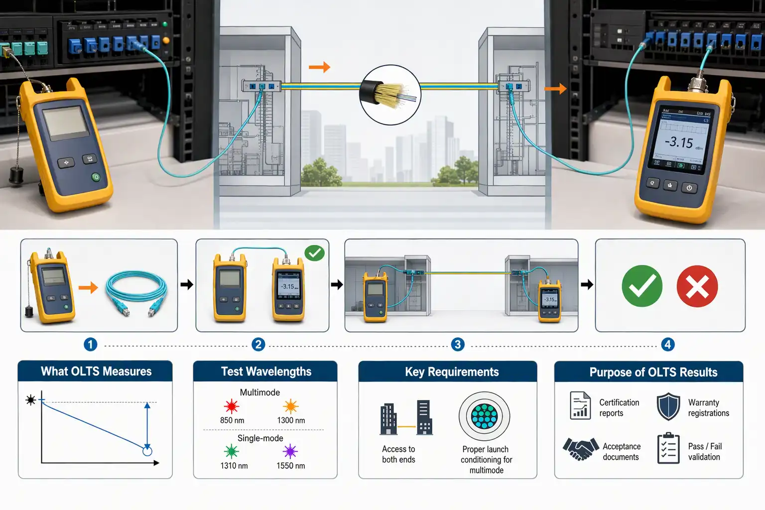
OLTS fiber testing measures the total insertion loss of a link by injecting light from a calibrated source into one end and measuring the light exiting the other end with a power meter. It is the most accurate and repeatable method for measuring overall link loss and forms the mandatory Tier 1 certification required by structured cabling standards.
A typical OLTS consists of a stabilized light source and an optical power meter, either as two paired instruments or as one integrated unit. The source is set to the wavelengths used by the actual application: 850 and 1300 nm for multimode fiber, or 1310 and 1550 nm for single-mode fiber. Before the measurement, the technician sets a reference using a reference test cord, and the measured insertion loss is then compared with the calculated loss budget of the link. The result is a clear pass or fail, which is why certification reports, warranty registrations, and acceptance documents are built around OLTS data. The method requires access to both ends of the link, and multimode measurements depend on proper launch conditioning to produce repeatable results.
OTDR vs OLTS: Key Differences at a Glance
The two methods differ in measurement principle, access requirements, and purpose: an OLTS directly measures total insertion loss from both ends and is required for certification, while an OTDR infers loss from backscatter at one end and is best suited for characterization, fault location, and troubleshooting.
| Attribute | OLTS | OTDR |
| Measurement principle | Direct transmission measurement with source and power meter | Inferred from backscatter and reflections |
| Fiber access required | Both ends | One end only |
| What it measures | Total insertion loss, length, polarity | Loss, distance, and reflectance of each event |
| Result format | Pass or fail against a loss budget | Graphical trace plus event table |
| Standards role | Tier 1, mandatory for certification | Tier 2, extended testing and troubleshooting |
| Skill required | Low, quick to learn | High, settings and trace interpretation |
| Speed | Fast, suited to high fiber counts | Slower, roughly ten minutes per direction per fiber |
When Do You Need Each Test?
Use an OLTS whenever a link must be certified against a loss budget, use an OTDR when you need to characterize a link, locate a fault, or verify individual splices and connectors, and use both together on projects that demand Tier 1 and Tier 2 documentation. The decision comes down to what question you are asking about the fiber and which ends of the link you can reach.
When an OLTS Is the Right Choice
An OLTS is the right choice whenever a link must be certified against a specification. New installations require Tier 1 testing of every fiber before handover, because the direct insertion loss measurement is the accepted proof of compliance for warranty and acceptance. Since the allowable loss depends on the equipment that will run on the link, reviewing Fiber Optic Connections with Transceiver Modules helps confirm that the measured margin matches the power budget of the planned optics. An OLTS is also the fastest tool for verifying large patching fields where both ends are accessible.
When an OTDR Is Essential
An OTDR becomes essential the moment a link fails and you need to know where the problem sits. It excels on long outside-plant spans with many splices, where a fault can be kilometers away, and on links with tight loss budgets where a single bad connector hidden inside the total loss figure must be isolated. Macrobends, fiber breaks, and degrading splices are all visible on the trace, which makes OTDR characterization valuable both during commissioning and as a stored baseline for future maintenance comparisons.
Why Using Both Together Matters
Certification standards such as ANSI/TIA-568 define these levels as Tier 1 and Tier 2, and the recommended workflow uses both in sequence. The OTDR first characterizes the link, exposing and locating problems while they can still be fixed; the OLTS then delivers the final certified loss value that proves compliance. Saving both the traces and the loss results in a single report protects the installer in later disputes and gives network owners a reference for troubleshooting. Skipping either half weakens the documentation: a loss value without a trace cannot locate future faults, and a trace without a certified loss value cannot prove the link meets its budget.
OTDR vs OLTS Testing in Real-World Network Scenarios
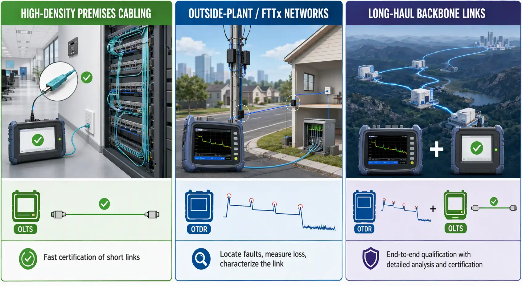
The right balance between OTDR and OLTS testing changes with the network environment: high-density premises cabling favors fast OLTS certification, outside-plant and FTTx networks depend on OTDR characterization, and long-haul backbone links require both methods working together. Looking at how the two instruments are applied in each scenario makes the choice concrete.
Data Centers and Enterprise Campuses
Premises environments are defined by short links, high fiber counts, and dense connector populations. Here the OLTS is the workhorse, because thousands of patch cords and trunk links must be certified quickly against the loss budget, and both ends of every link are always reachable. Trunk links between switching floors are frequently specified with Tier 2 testing as well, since the OTDR trace records exactly which of the many connectors in a channel is degrading. High-fiber-count parallel optics also call for testing all fibers of a multi-fiber connector simultaneously to keep project timelines realistic.
FTTx and PON Networks
Passive optical networks present a different challenge: a splitter divides one feeder fiber into many drops, and the drop ends sit behind customer wall outlets that may not even exist at installation time. An OLTS is still required to certify the feeder and distribution sections against the class loss budget, but the OTDR becomes the primary characterization tool from the central office, revealing the splitter loss, splice quality, and any break in the feeder before subscribers are connected. Testing in planned stages, first the feeder and then each distribution branch as it is activated, keeps the documentation aligned with the build schedule.
Long-Haul and Metro Backbone Links
Long spans accumulate dozens of splices and multiple patch panels over distances of tens or hundreds of kilometers, which makes a per-event view indispensable. Every fiber in a Long Haul Fiber Optic Solution is typically characterized with an OTDR in both directions at commissioning, so that each splice and connector is verified against its individual loss limit rather than hiding inside a passing total. The OLTS then confirms the end-to-end loss against the amplifier power budget, and the stored traces serve as the baseline for comparing future measurements when a span starts to degrade.
Best Practices for Reliable Fiber Test Results
Reliable fiber test results come from disciplined preparation: inspect and clean every end face before mating, set references and OTDR parameters correctly for the link, test in both directions where required, and archive every result. The instrument can only report what it is given, so procedure determines the quality of the measurement.
The most common cause of failed tests is contamination, so end faces should always be inspected and cleaned before mating, including new connectors straight from the bag.
- Inspect and clean every connector end face before testing, then re-inspect after cleaning.
- Set the OLTS reference correctly with the method specified for the job, and verify reference leads before starting.
- Choose OTDR wavelength, pulse width, and averaging time to match the fiber length and event spacing.
- Average OTDR loss measurements in both directions to compensate for backscatter differences.
- Store all traces and results as permanent documentation of the as-built link.
FAQ
What are the three ”C“s of fiber?
The three ”C“s of fiber refer to its structure: the core, the cladding, and the coating. The core is the light-carrying center of the glass, the cladding surrounds it with a lower refractive index that guides light through total internal reflection, and the coating is the protective outer layer. Contamination of the core region during mating is the leading cause of excess loss and test failures.
Which fiber optic tester is considered the best?
There is no single best fiber optic tester, because each tool answers a different question. An OLTS is the most accurate instrument for certifying total insertion loss, an OTDR is the most informative for characterizing and troubleshooting a link, and a visual fault locator is the quickest way to check continuity on short runs. A capable OTDR System combined with an OLTS covers the full range of field needs.
Can an OTDR Replace an OLTS for Certification?
No. Standards bodies require Tier 1 insertion loss testing with an OLTS because the OTDR value is inferred from backscatter rather than directly measured, and it is less repeatable, especially on short multimode links. An OTDR is a powerful addition for characterizing events and locating faults, but the certified pass or fail figure for a link must come from a light source and power meter measurement.